Skip navigation

Tag Archives: Commodore

I’m a huge fan of the Amiga line of computers and I own most of the various models released during its time in the sun. The Amiga 2000 (I’ll refer to it as the A2000 from here on out) eluded me for years though. Finally, a few years back I was able to acquire an A2000 which is what I will be showing you in today’s article.

The A2000 released in 1987 is basically an Amiga 500 placed in a desktop case with expansion ports. Now keep in mind that is a bit of a simplification but the 2000 and 500 use mostly the same chipset and devices that are compatible with the A500 will generally work with the A2000. Also, keep in mind that there were some variations of the A2000 such as the A2000HD, A1500 and the A2500 which are more or less A2000’s with different stock options. The A2000 was mostly marketed as an Amiga for the professional or business market where the A500 was seen as more of a consumer level product.

I’d say the front of the A2000 is pretty unremarkable and looks like a rather bland standard PC case. On the left side of the case are two LED lights labeled power and hard disk. The standard A2000 actually did not come with a hard drive through the A2000/HD did come with one standard via a 2090 controller card and SCSI drive. My A2000 here was upgraded with an HD which we will look at later. There is room for two 3 1/2 drives as well as one 5 1/4 bay. A2000’s came standard with only a single 880KB double density floppy drive as we can see on mine.

Beneath the drive bays are a 5-pin AT style keyboard port as well as dual DE-9 ports. I have a converter in my A2000’s keyboard port so I can use my Amiga 4000 keyboard as I lack an original A2000 keyboard. For the DE-9 ports I generally attach an Amiga mouse as well as a nice Wilco Commander joystick.

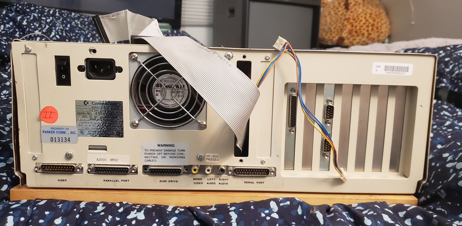
Here is the rear of the A2000. I did remove one of the metal slot covers and currently have a power lead as well as the floppy cable coming out of the back. I will explain that later in the article but for now let’s just ignore it. Let’s take a look at the conveniently labeled various ports below the power supply and the standard 3 prong power connector.

Starting on the left we have a DB-23M analog RGB video out connector for attaching your Amiga to a compatible RGB monitor. Next we have a parallel port as labeled followed by a port to attach an external floppy disk drive. Next we have three RCA A/V out ports. The first of these ports is a mono composite out jack. Keep in mind this port only outputs a composite video signal in black and white. The reason for the black and white output as opposed to color is the A2000’s intended primary market being business professionals. In the mid 1980’s many businesses were still using monochrome monitors for the mostly text based work and the feeling was that color composite would largely be wasted on the A2000. The video out is followed by dual left and right stereo audio out jacks. Lastly we have an RS-232 serial port.

Removing the cover reveals the power supply as well as drive bays and my two currently installed expansion cards which we will talk about a little later.

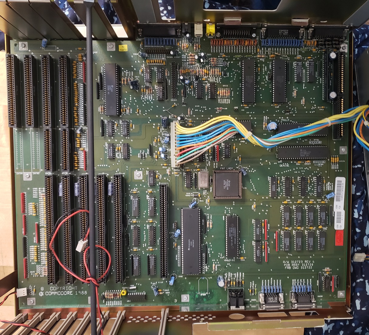
Removing the power supply, drive bays and expansion cards reveal the motherboard of the Amiga 2000. I have a revision 6 motherboard in my Amiga, other revisions of the board may vary somewhat.

1) CPU – The CPU of the A2000 is the Motorola 68000 at 7.16MHz. This is the same CPU and speed as the best selling little brother of the A2000, the Amiga 500. The CPU is socketed and can be replaced with a Motorola 68010. The 68010 offers a small speed boost though the exact amount seems to vary by the source. I’ve read the boost can be anywhere from a negligible 2% all the way to 10%. The 68010 was also popular with users of the WHDload program as it allowed escaping from games without restarting though later versions of the program are said to of fixed this issue allowing closing out games even on the original 68000. Replacing the CPU with the 68010 was also known to cause a small amount of incompatibility with games and generally was not worth the small speed bump.

2) ROM chip – Depending on your model of A2000 the ROM chip could vary but they generally came with a 256k or 512k ROM chip. The kickstart chip determined what Amiga OS could run among many other things. My A2000 came with a V2.04 512k ROM. These ROM chips are also socketed and can be replaced with older ROMs (for compatibility) or newer ROM chips depending on your needs. There are even dual ROM chips that allow users to choose if they would like the machine to boot up using an older or newer ROM version.

3) Agnus chip – The Agnus chip is a part of the Amiga’s custom chipset which allowed for many of the Amigas advanced features for the time. Agnus was responsible for a variety of tasks such as acting as a memory controller, system clock generator, DMA controller and many other tasks. This chip will vary depending on your Amiga 2000. My Agnus is the 8372A “Fat Agnus” which is a 1MB chip and a part of the ECS chipset (discussed later). This version of Agnus can address up to 1MB of chip RAM but earlier versions only supported up to 512MB of chip RAM. There are also later 2MB versions of this chip which usually are found in Amiga 3000 and 600’s. From what I’ve read you can upgrade this chip on an A2000 to a 2MB “Super Fat Agnus” but most methods seem to require some modding which includes soldering.

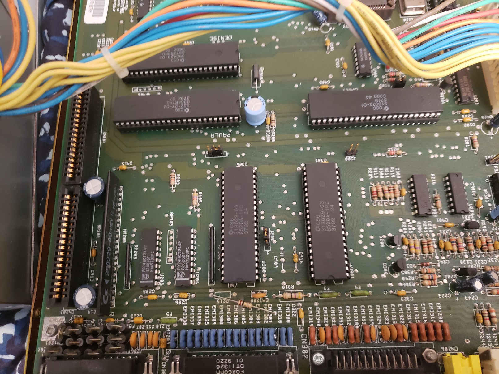
4) Gary, Paula, Denise chips – These three chips make up the bulk of the Amiga’s custom chipset and each chip helps to control various aspects of the computer’s functionality. Without getting super technical we will go over the basic functions of these chips.

Gary – System address decoder

Paula – Audio and I/O controller

Denise – Display encoder

My Amiga came with a “Super Denise” chip installed and with the previous “Fat Agnus” chip give my A2000 the ECS chipset or Enhanced chip set. Earlier A2000’s came with the older OCS or Original Chip Set. The ECS only offers fairly minor upgrades over the OCS such as the ability to address more chip RAM, allow for a few higher resolution modes and allowed software switching between 50 Hz PAL and 60 Hz NTSC modes.

5) RAM – My A2000 is a rev 6 motherboard and came with a full 1MB of “chip RAM” soldered onto the motherboard. Amiga chip RAM is shared between the CPU and the custom chipset while Amiga “fast RAM” is assessable only by the CPU. Earlier A2000s usually shipped with 512k of chip RAM and 512k of fast RAM. Some programs do specifically require a full 1MB of chip RAM while fast RAM is relatively easily addable via the Zorro expansion slot cards. 

6) Floppy drive controller chips

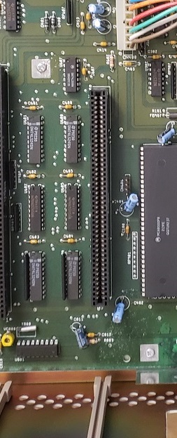
7) Buster chip – The Buster chip (the large vertically positioned chip on the right side of the image below) is another of the Amiga’s custom chips. “Buster” is the DMA arbitrary controller. To the left of the Buster chip and below the power connector are two internal connectors for the floppy header and an internal serial header.

8) Expansion slots – The expansion slots on the A2000 are interesting in that they include several mostly unused PC ISA slots alongside the five proprietary Amiga ZORRO II slots.

The five Zorro II slots support a large variety of Amiga expansion cards and support bus mastering DMA as well as an autoconfig protocol similar to “plug and play”. The ISA slots can only become active by the use of a bridgeboard.

Processor Card Slot – sitting away from the Zorro II slots and next to the CPU chip is a short slot resembling an 8-bit ISA slot. This is the Processor Card Slot.

With this slot you could add various CPU accelerator cards, some featuring co-processors, memory, ect.

9) Power connector

10) Video slot – This slot is used to add various video cards such as Genlock cards, deinterlacers or the “Video Toaster” card. It wouldn’t be correct to think of this in the terms of a PC where you could add better video cards to assist in gaming as this slot was meant for cards that assisted in things like video editing and effects.

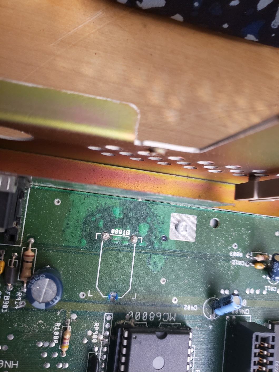
11) CMOS battery – This is the internal CMOS barrel battery for saving time/date information. Mine was removed some time ago. This can be modded for a coin style battery.

My A2000 came with two Zorro expansion cards installed by the previous owner.

The first card is just a dual serial port card that adds two additional serial ports to the Amiga.

The second expansion card is much more interesting and useful.

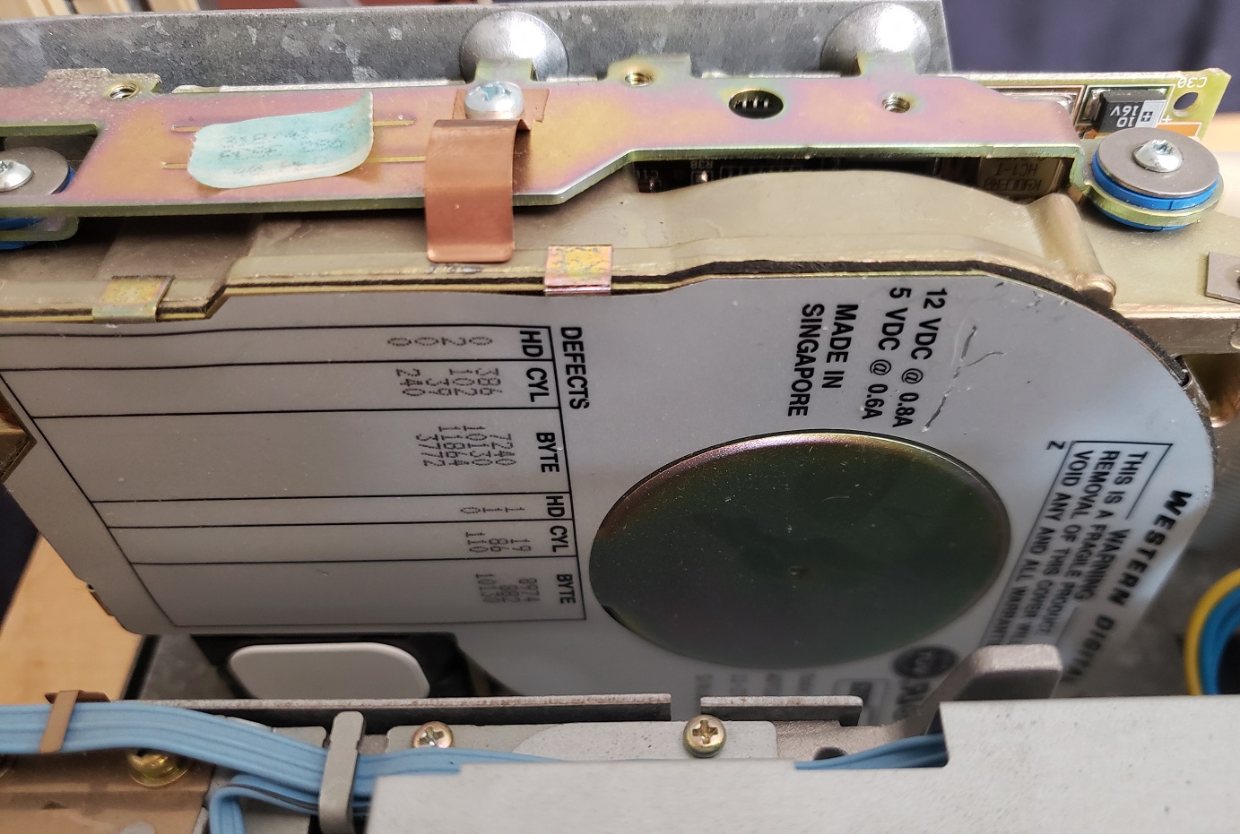
The second card is a GVP A4008. The GVP A4008 is a pretty nice Zorro II SCSI controller card (50 pin SCSI header) and also allows the adding of up to 8MB of “fast RAM” to the Amiga. This is not the HDD controller card that came stock in A2000/HD units but it effectively turns this Amiga into a 2000/HD as well as allowing extra RAM. My card came with a 50MB SCSI drive and 2MB of RAM. I believe my A2000 formerly belonged to a Krogers grocery store as on booting up from the hard drive the machine loads up what appears to be grocery store advertisements. I have since upgraded the hard drive to a 2GB SD card via a SCSI2SD adaptor and have also maxed out the RAM to 8MB.

UPGRADES

Other than replacing the hard drive with an SD card and upping the amount of fast ram to 8MB I have also performed a few other upgrades to the A2000.

Floppy Emulator drive.

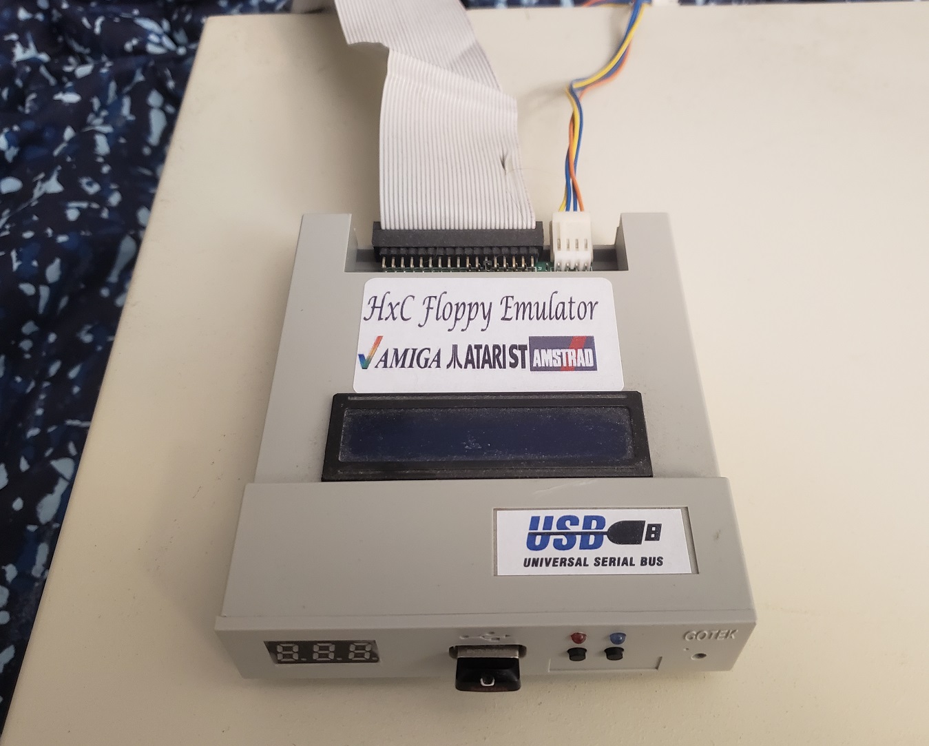
In my experience Amiga floppy disks seem to fail much more common than the PC variety. Thankfully there are answers to this problem in the form of programs like WHDload which lets you install games to a hard drive as well as floppy drive emulators which allow the use of USB flash drives to act as floppy disks. Unfortunately I feel that adding these emulator drives ruins the classic look of the machines. On something like an Amiga 500 where the disk drive is on the side of the machine this isn’t so bad but on a forward facing A2000 it’s just kind of hideous in my opinion.

Because of this I have opted for an external floppy drive emulator. It’s still not the most elegant solution but it maintains the classic look of my A2000. To achieve this I currently have the actual floppy drive in my Amiga disconnected and rerouted the floppy cable out of the back of the Amiga to the emulator. There are mods available that allow you to add a switch to change the main floppy drive to the external floppy port but I haven’t had much luck with these mods.

Next I have replaced my original ROM chip with a dual kickstart ROM that allows me to choose kickstarts via a switch.

The ROM is dual KS 1.3 and 3.1 thus I can use it to take advantage of the enhanced features that KS 3.1 provides while retaining the ability to drop back to KS 1.3 to maintain compatibility with some older games and programs.

The Amiga 2000 is one of my favorite Amiga’s as it shares most of the same specs as the ubiquitous Amiga 500. It retains a very high level of compatibility with games while at the same time it allows for both more and easier expansion options such as adding more memory and things like hard drive and CD drives. Like most Amigas the A2000 can be hard to come by as well as demand a premium.

Some time ago we took a look at another Commodore branded PC, the Commodore Colt. Today we will be looking at its more powerful brother, the Commodore Select Edition 286 also sometimes known as the PC40-III.

As you can see from the image above my Select Edition 286 is in pretty terrible condition and is covered by a residue that seems to be from some kind of adhesive tape that was once all over this PC. On the front we can see that things are pretty basic with two small power and HDD activity LEDs as well as the Commodore badging. I have seen several variations of the case with the “Commodore Select Edition 286” badging online though, so the look of your PC may vary from this one. There are only two 5 1/2 bays both being occupied by floppy drives. The top drive is a 1.2MB 5 1/4 floppy drive while the bottom is a very mangled and non-functioning 1.44MB 3 1/2 floppy drive.

When I picked this machine up it also came with an official Commodore branded keyboard which although a bit dirty is in much better shape then the PC itself.

Like other Commodore PC compatibles of the era the keyboard port is located on the side of the PC next to the reset button. This can be annoying when opening the case as the reset button does get in the way when removing the cover so you have to take care to press the button down and then slide the case cover over it and off.

The back of the Select Edition 286 is fairly bare as well. The power button is located above the power jack. To the right of these we have a label which interestingly marks the model as a PC30-III. Starting on the far lower left we have what looks to be a serial port for a mouse though my suspicions are that like the Commodore Colt this port is actually for an Amiga style mouse. As I could not get this particular machine to get past POST I was not able to test this. Next to this we have a single RCA jack labeled “Audio”. On the Commodore Colt this port was a composite video out port. I would assume on the Select Edition 286 this port has been rewired to output the speaker sound via an RCA output but again, I was unable to test. The area next to the RCA jack has been patched closed. On earlier machines this is where the video out and switches for video mode selection would have been. Next we have a serial port followed by a parallel port. Finally we have four expansion ports, one of which is currently taken up by a video card.

Here we have the Select Edition with the top case cover removed. We can see to the right of the floppy drives a mounted hard drive and on the motherboard we can see our four expansion slots, one 8-bit and three 16-bit ISA.

The installed hard drive is a Western Digital although I never pulled it to check the model number. It’s likely a 30-40MB hard drive give or take.

Here we have the motherboard exposed with all the bays out of the way. The yellow sticker at the center of the board marks it as a PC30-III though the silk screening on the board itself, between the ISA slots, marks the board as a PC40-III.

1 ) CPU – As one would expect from a PC labeled as a “Select Edition 286” the CPU is a Siemens 286 running at 12MHz. The CPU itself in this machine looks very worn and I was barely able to make out the speed. 12MHz is a pretty healthy speed for a 286. While not as beefy as a 16 or even 20MHz 286 the 12MHz is speedy enough to allow one to play a large variety of EGA and even VGA games at acceptable speeds.

2 ) FPU socket – This would be where you would add a 287 math co-processor. In terms of gaming adding a 287 is mostly pointless as very few games that would run well on a 286 support it (Sim City), though it would be useful for running things like CAD.

3) RAM – The Select Edition 286 comes with a full 1MB of memory on-board, at least if your to trust the setup screen. Having any chips soldered directly to the board is usually a disadvantage to the user since it makes replacing failed chips more difficult. 1MB is a healthy amount for the time but to play some later games your probably going to want to add a few more MB via an ISA expansion card.

4 ) floppy / IDE connectors – Controllers for both IDE and the floppy are built into the motherboard. This is something that wasn’t even a given all the way into the 486 era so it’s a nice feature to have built in. This is extra nice since we only have four ISA slots to work with and not having to take one up with an I/O controller card is certainly a plus.

5 ) Dallas RTC – Unfortunately the Select Edition 286 uses a soldered Dallas RTC battery to save its CMOS settings. The battery is long dead preventing the PC from progressing past the POST screen. It is possible to desolder the battery and solder in a socket or solder into the battery and connect a coin battery.

6 ) Video switch – The video switch is leftover from the earlier machines which share the same motherboard. On the Select Edition 286 Commodore decided to ditch the built in video and go with a discrete EGA card in an expansion slot. I attempted to install a VGA card and was unable to get video though adjusting this switch may of solved the issue I did not attempt it.

7 ) Pizo speaker & Power connector – Commodore went with a cheaper pizo speaker as opposed to a cone speaker for this PC. The power connector like the Colt and probably other Commodore IBM compatibles uses the Amiga style power connector making things inconvenient if your original PSU should die.

The card that came with my PC was a 8-bit ATI EGA Wonder 800+. The 800+ is an interesting card as it is more or less a VGA Wonder card cut down to work as an EGA card. The card has 256K of video memory and supports various video modes including SVGA 800×600 in 16 colors. The card is also jumper free and switchless and is configurable via software.

Overall the Commodore Select Edition 286 is a completely usable 286 machine with decent speed and nice built in features. There are a few annoying things that make it a bit less useful then a more generic 286 board though, such as the lower ISA slot count as well as the Amiga style mouse port and power connector. Unfortunately I was unable to get my machine up in running for this article due to the Dallas RTC and the POST loop it locked me in which is a shame. Of course this can be fixed with a mod but I decided to use my time and resources elsewhere.

Were you a huge fan of the best selling Commodore 64 computer in the early 80s? Did you love it so much you just wished you could bring it along everywhere you went? Well, if so, in 1984 you were in luck because that’s when Commodore released the SX-64 or sometimes called the Commodore Executive, a Commodore 64 “luggable” computer. The SX-64 was a Commodore 64 computer, complete with floppy disk drive, keyboard and a small 5 inch color CRT monitor all in one briefcase style package. It was heavy and bulky like a large briefcase and still required the unit to be plugged into a wall power supply but in the early 1980’s this was the norm for portable computers.

The keyboard of the SX-64 also acted as the front cover and attached over the front of the machine shielding the monitor and single floppy drive. The handle on the case doubles as a stand when the SX-64 is in use.

With the front cover / keyboard removed by pressing down and two small plastic tabs the front of the SX-64 is revealed. On the far left we have the 5 inch composite color CRT monitor. Next to that we have one Commodore floppy disk drive and what looks like a storage area above it which is actually….well, a storage area and is labeled as such. There were plans to release a SX-64 with two floppy disks drives named the DX-64 but details are a bit sketchy on if this version was ever actually officially released. A few have turned up over the years but they seem to be exceptionally rare. I’ve read some SX-64 owners have indeed added a second drive in the “storage area” so it can be done. Usually this little storage bay is used to stow the keyboard cable when the SX-64 is not in use.

On the far right we have a small door with the C64 branding behind which is some basic control knobs and pots to control sound volume and adjust the monitor.

The 5” color composite monitor itself is small but very easy to read and I found mine to be quite sharp and gave a better looking image then I expected.

This slideshow requires JavaScript.

Spinning the SX-64 around we can take a look at the back and the various ports.

Starting from the left we have two joystick / mouse ports followed by an A/V out port meaning that you can easily connect the SX-64 to an external monitor or TV if you wished. Next to this is a Commodore serial 488 port for connecting things like an external disk drive or printer. In the center we have the edge connector like Commodore user port which connects to some printers, modems or even other computers. Lastly to the far right we have a standard three prong power connector, a fuse and a power on/off switch. My unit interestingly does not have the port labels molded into the plastic next to the relevant ports where I have seen some models that do.

Located on the top of the SX-64 is the cartridge port.

The keyboard connects to the main unit via a non-standard 25-pin keyboard connector. The connector on the SX-64 itself is located below right side of front panel and is a little awkward to reach and connect in my opinion.

Finding an official replacement cable if yours is lost or damaged can be difficult but homemade replacements can be found on eBay in the $25 and up price range. They generally aren’t as nice looking as the official cables though.

Lets take a quick look inside by removing several screws on the side.

This slideshow requires JavaScript.

The internals of the SX-64 are extremely cramped and hardware failures due to excessive heat are not uncommon. On the left side we mostly have the CRT itself as well as the speaker and behind that the power supply. Directly behind the cartridge slot is the board with the keyboard controller and the panel on the far right is the board hosting things like the CPU, RAM and PLA chip.

Common issue with PLA chip

On powering my SX-64 up for the first time however I was greeted by a very pixelated and distorted screen.

This is a rather common issue caused usually by heat and a faulty PLA chip. Thankfully this chip is socketed and is fairly easy to get to and replace.

Below is an image with the bad chip highlighted. Even though it’s relatively easy to reach you probably are better off disconnecting the board and raising it out of the case for better access. There are some excellent guides online and on YouTube detailing this process.

And here is the offending chip once removed.

I opted to replace my PLA chip with a more modern equivalent. I found my online for about $25 and as far as I can tell it is 100% compatible and generates significantly less heat.

I even decided to add a small heatsink just for extra cooling though with a more modern replacement part like this it’s not necessary.

If you experience keyboard issues you may also want to make sure the connection with the board directly behind the cartridge slot and the main board are making a solid connection as seen below.

Thankfully this simple and fairly cheap fix solved all my video issues and if you have issues with your SX-64 I would suggest looking at replacing the PLA chip first. There are other chips that may go bad including the RAM which unfortunately is soldered on but I have found a bad PLA chip is usually the issue as far as a black or distorted screen goes.

Overall compatibility with the SX-64 seems to be pretty good though I’ve read there are issues with certain games and peripherals such as RAM expansion units and some printers. Due to the default screen color being changed to blue text on a white background some programs may experience issues since they expect the default white text on a blue background.

I like the SX-64 but I don’t really find it that useful as I would strongly prefer a standard C64. The SX-64 didn’t sell that well back at release. The C64 was never really seen as a serious business machine and in my mind packing a breadbox C64 as well as the floppy drive, PSU and a few cables into a small box and just using a larger TV as a monitor if you’re going on vacation or something isn’t much more of a hassle or less of an inconvenience then lugging the SX-64 with you. Yes, it is more convenient and if you needed a C64 and traveled a lot or did demonstrations it would be really helpful but for a retro gamer today it’s an interesting piece for Commodore fans but I’d stick with a good old C64 or C64c for my actual C64 gaming.


colt1

Commodore is best known for thier unique series of home computers such as the VIC-20, Amiga, PET and best selling Commodore 64 but like all PC manufactures in the the earlier years Commodore had its tentacles in the world of PC clones as well. One such PC clone (or more specifically turbo XT clone) from Commodore was the Commodore Colt which is a rebranded Commodore PC10-III. Maybe a group of executives figured a cool name slapped onto a new case would move more units then the boring and business sounding  PC10-III. From what I can find the PC10-III was launched in 1987 and used the exact same motherboard as the Colt and only the case and name were different. The PC20-III also used the exact same motherboard and was merely a PC10-III with a factory installed 20MB hard drive. From the rest of this article on when I refer to the Colt the same things apply to the PC10 and PC20 III’s. Despite being a PC clone machine the Colt has a number of unique quirks and features giving the machine a personality of its own.

colt2

I found my machine as far as I could tell completely factory stock and in great physical and working condition. The front of the PC has a Commodore logo and badge as well as activity lights for a hard drive and power. There is no power button on this machine or reset button so powering on and off is done via a switch on the back which admittedly is a bit of an inconvenience. There are two half height 5.25 drive bays. The Colt came stock with either one or duel 360K drives like mine does. both of my drives thankfully worked perfect.

colt3

The keyboard port is not located on the rear of the machine but on the right side of the case. The mouse port on the Colt is for a 9 pin D-sub bus mouse port and is compatible with the 1352 mouse which happens to be the same mouse used with the Amiga. This appears to the system as a bus mouse and standard MOUSE.COM drivers in DOS should work just fine. Next is the built in Video which uses a composite out jack for a composite monitor and a 9 pin video port for CGA via the onboard Paradise PVC4 chip. There are a few DIP switches next to the video port to set the video along with an extremely handy chart on what the settings are which was good thinking on Commodores part. Next is a 25 pin serial port and finally a printer port. There are a measly four expansion card ports but even worse the motherboard itself only has three ISA slots which we will see in a minute. Powering all this is a proprietary form factor 75 watt power supply.

Here is a quick look at the green screen monochrome monitor that came with my Colt. The picture quality was very good and this monitor was very light.

coltm1

coltm2

The Colt case is fairly easy to remove after a few screws are removed.

colt4

Now that the case is off we can see there is room for an internal drive which is slightly uncommon for an XT class machine as usually the case expects you to be mounting a half height MFM drive in one of the 5.25 inch bays though will get our explanation for this as we open up the case more.  Another thing we can notice is the lack of expansion ports. The Colt sports only three 8-bit ISA slots which is about the smallest I’ve seen for a machine of this form factor. This deficiency is somewhat made up for though with the multitude of good quality built in features like the quality CGA video and built in floppy controller.

colt5

Here is the exposed motherboard. You can see the keyboard port on the bottom of the image. The board itself is overall pretty well made and compact.

1) CPU – The Colt uses an 8088-1 CPU capable of 10mhz speeds. The really cool thing about the Colt is that its Faraday FE2010 chipset allows the CPU speed to be adjustable via a SPEED.EXE utility via DOS or through keyboard commands. The default is the standard 4.77mhz but the speed is adjustable to 7.16mhz and 9.54mhz

  • CTRL+ALT+S switches the CPU to the “Standard” 4.77MHz speed
  • CTRL+ALT+T switches the CPU to the “Turbo” 7.16MHz speed
  • CTRL+ALT+D switches the CPU to the “Double” 9.54MHz speed

This is a really nice feature that helps give a boost to programs that need it and giving the best compatibility. Most machines I’ve encountered have only offer two speed settings, usually 4.77mhz and 7.16mhz. The Colt like almost all 8088 machines can be upgraded via an NEC V20 CPU giving a significant speed boost at the slight cost of game and program compatibility.

colt6

2) NPU – This is the math co-processor slot if one should choose to add an 8087. This obviously gives a boost to programs which use the extra math power of the processor though almost no games of the era use this feature. If adding a math co-pro be sure its the 8087-1 variety that is capable of 10mhz else you may encounter instability if running the machine at 9.54mhz “double” speed.

3) RAM – The Colt comes with a full 640k of memory on-board which is the full amount a XT PC can address and more then enough for the CGA era. More RAM can be added via expansion cards but like the math co-pro nothing this early takes advantage of the extra memory and it’s really a waste of the few ISA slots this machine does have.

4) PSU – This is the proprietary power connector for the power supply which can present a problem if your Colt’s power supply is dead or dies. A standard AT power supply, provided it fits could possibly be modified to work.

5) Video – The onboard video features the Paradise PVC4 which functions pretty much just like an ATI small wonder CGA card. The layout is actually the same as on the small wonder cards and  it could be that Paradise produced the actual chips for the small wonder cards but I haven’t been able to confirm this. The onboard video offers the same modes as the small wonder cards by outputting CGA composite via the RCA jack as well as MDA, CGA Color text and graphics, Hercules monochrome, Plantronics Colorplus and Alpha132 Monochrome via the 9 pin video port. This is one of the few times I didn’t upgrade the video in a PC since the go to card for me on an 8088 would be a ATI small wonder CGA card but in this case it wouldn’t offer any benefit over the onboard video and would eat one of the precious three ISA slots.

colt7

6) XTA interface for hard drive – Now this is a very interesting feature of the Colt and probably why we see a small internal bay for a 3.5 inch hard drive. At first glance the connector next to the floppy drive interface may look like a more modern IDE connector but it’s actually an 8-bit variant known as XT or XTA IDE. The connector looks the same as IDE and should fit the same cables but unlike the 16-bit variety we are used to seeing this short lived 8-bit IDE standard will only work with a very small number of drives. There may only be about twelve or so models built to work with this standard and they are all old, unreliable, small in size (20mb or under), hard to source and probably massively overpriced. As neat as it is having built in IDE on a 8088 machine, due to the factors I’ve already stated it’s best to disable the onboard  interface via jumper JMP208 and seek out a controller card instead.

colt8

7) Floppy drive interface – This is the built in drive interface. The floppy controller on the Colt cannot be disabled to allow for a separate card to be used and this controller does operate differently then a standard controller. It supports 360k drives which is usually what the Colt came stock with but it also supports 720k drives. Adding a 720k drive can be a difficult task and the process is a little more involved then in other XT clone machines. If you’d like to learn about this scroll down to my upgrade section where I will be covering this.

8) Speaker – unfortunately the Colt does not feature an actual cone PC speaker but instead a piezo beeper speaker

I want to go over a few upgrades I did with my machine that I think make it a better all around PC to work with giving me more flexibility and an overall improved experience.

The operating system I have installed on my machine is MS DOS 3.2 which is the original OS distributed with the Colt.

UPGRADES

CPU – The first question I had with the Colt was whether I wanted to replace the 8088 CPU with a NEC V20. As I’ve said in just about every 8088 review I’ve done the NEC V20 upgrade is generally recommended and offers a speed increase (up to 15%) at only the cost of slight compatibility with a few very speed sensitive games and programs. For my Colt though I decided to stick with the 8088-1 for full compatibility speed wise with the CGA games I plan on playing on this machine. I also installed a Intel 8087-1 math co-pro though it will likely see little usage.

Hard Drive – for the hard drive I used the Silicon Valley APD50L  8-bit hard disk controller that I previously had installed in my Epson Equity E1 PC. This card should give slightly better performance than a IDE-XT card. I ended up pairing it with a industrial grade 32MB CF card. I generally do not use CF cards with most of my systems but I felt it really benefited here with its speed and much lower power draw. My Colt fortunately came with its original working floppy disks so I was able to install MS DOS 3.2 with the Commodore SPEED utility. 32mb is also the max size partition limit for DOS 3.2 which I think is far more then enough space seeing as I will be using this machine with early 80’s games and most programs of the time  are very small.

colt9

Sound – Since sound cards didn’t become a thing until the late 80’s a sound card in an early 8088 based XT machine is far from necessary. Pretty much everything you can run is going to be PC speaker only. Seeing as this was going to be my new all around XT PC though I wanted the option in case I wanted to play something like a demo or something like Prince of Persia in CGA mode. To that end I installed a Sound Blaster 1.5. The 1.5 is an 8-bit Sound Blaster card which is identical to the SB 1.0 except that the Creative Music System compatibility was dropped. Thankfully this can be restored giving high CMS compatibility by adding two cheap Phillips SAA-1099s into the two empty sockets. This is much easier to achieve then with the later SB 2.0 which also requires a hard to find GAL chip. I like the sound blaster because it gives me Adlib, CMS and SB support if I so choose.

colt10

Adding a 720k floppy drive

colt12

now I’m going to make this a section of its own since as I stated earlier the process is a little more involved on a Colt then a regular XT clone. Although the onboard controller does indeed support 720k drives how it goes about this is different. First off I wanted to keep my drive A: as a 5.25 drive since this is the primary format of the era and most of the PC booter games I have are this format of which many require the booting drive to be A:\. Before I go any further I also want to thank the good people over at the Vintage Computer Forums and especially Scali and SkydivingGirl for helping the retro community figure this process out as it was not well documented at the time.

You may notice that the floppy drive cable that came with your machine lacks a twist found in most other floppy cables to help the machine differentiate drive A from B. The Colt instead uses jumpers on the floppy drives themselves to make this distinction (DS0 for A: and DS1 for B:). Note that using a standard cable with a twist will NOT solve this issue as the motor on signal to the floppy is also done differently at best only one drive will work.

colt13Original cable with two 5.25 floppy edge connector

First off I have only done this with the original Chinon FZ-502 5.25 drive as drive A: so I’m not sure how it would perform with a 3.5 drive not being B:. make sure your 5.25 drive is jumpered as DS0 and leave everything else as default.

Next your going to need a 5.25 to 3.5 inch bay converter so your 720k drive will fit in the 5.25 inch bay. For simplicity I also acquired a 34 pin to edge connector converter like the one below so I wouldn’t need to mess around with a different cable. I acquired mine at http://www.bgmicro.com/

colt15

 Lastly your going to need a 720k drive with jumpers. I went with a Chinon FZ-357 drive but I can confirm a Chinon FZ-354 also works in 720k mode as well as a Gotek SFRM72-FU-DL 720K floppy emulator. The jumpers on drive B: need to set very specifically for it to work. Make sure you close the DS1, MD, DC, and TTL/C-MOS jumpers as below.

colt14

If done correctly you should now have a fully working 720k floppy drive in your Colt or PC10/20-III PC.


Adding an XTA hard drive

As stated earlier, if you want to use the onboard XTA hard drive interface your going to be very limited on what drives you can use. Possibly the best choice is the Seagate ST-351A/X drive.

colthdd1

First off remember to set the onboard jumper JMP208 to enable the onboard interface. make sure its jumpered to the pins that are in line with the other jumpers beside it. If you have an early BIOS revision of 4.35 like mine your going to be limited to 20mb of space at most.  With the ST-351A/X  you must set the drive to XT mode. My drive is jumpered in the following way.

colthdd2

After the drive is jumpered and attached correctly you should not get a “hard drive not found” message on the boot BIOS screen anymore. There’s a few more steps though from this point.

Boot the PC from a floppy disk and when you get to the A:\ prompt run DEBUG.EXE.  which will take you to a “” at the prompt type G=FA00:5 and press enter. hit enter for the next few questions that come up. When asked about dynamically configuring choose N and lastly hit Y to begin low level formatting.

If everything is set up OK and the drive is in working order the program should low level format your drive. After a reboot you need to run the FDISK program to set a partition. after setting a partition use the FORMAT command. type FORMAT C: /V/S which should be the final step to allow you to boot from and use your hard drive.

colthdd3

colt16

Overall the Colt is a nice looking, reliable and compact XT clone. Its hampered by its lack of expansion slots but this issue is mitigated somewhat by the quality onboard options. The three CPU speeds are probably one of the neatest features I’ve seen in any XT class machine and I love the flexibility it affords me. The hassle with adding 720k floppies does detract from the usefulness of the Colt plus the virtual uselessness of the built in XTA hard drive interface makes the option pointless for the most part. They are neat machines and with a little effort can be made into very competent 8088 XT PC’s but in honesty unless your a die hard Commodore fan like myself, crave the coolness factor or stumble across a working one for super cheap its probably not worth the hassle. A generic XT PC can be had easier without the odd floppy issues and with far more expansion card possibilities.

This slideshow requires JavaScript.

FDISKformat

A place for the pc collector

I ❤ Old Games!

Probabilmente il miglior blog bilingue al mondo*

Waltorious Writes About Games

Game-related ramblings.

NekoJonez's Gaming Blog

My Gaming Timeline

Evelynn Star

Lynn talks about video games, records and books ...

Retro Megabit

Sharing My Retro Video Game Collection.

133MHz's Junk Box

Random electronics and gaming crap

SNES A Day

Chronogaming project featuring reviews, screenshots, and videos of the entire Super Nintendo library in release order.

Retrocosm's Vintage Computing, Tech & Scale RC Blog

Random mutterings on retro computing, music, plus radio controlled scale modelling.

The PewPew Diaries.

Work(s) in Progress!

1001Up

1001 video games and beyond

retro computing and gaming plus a little more

sparcie

retro computers and stuff

jispylicious

Stay Jispy!