In today’s article, we will be looking at the Packard Bell Legend 605, an 80486 class computer from Packard Bell.
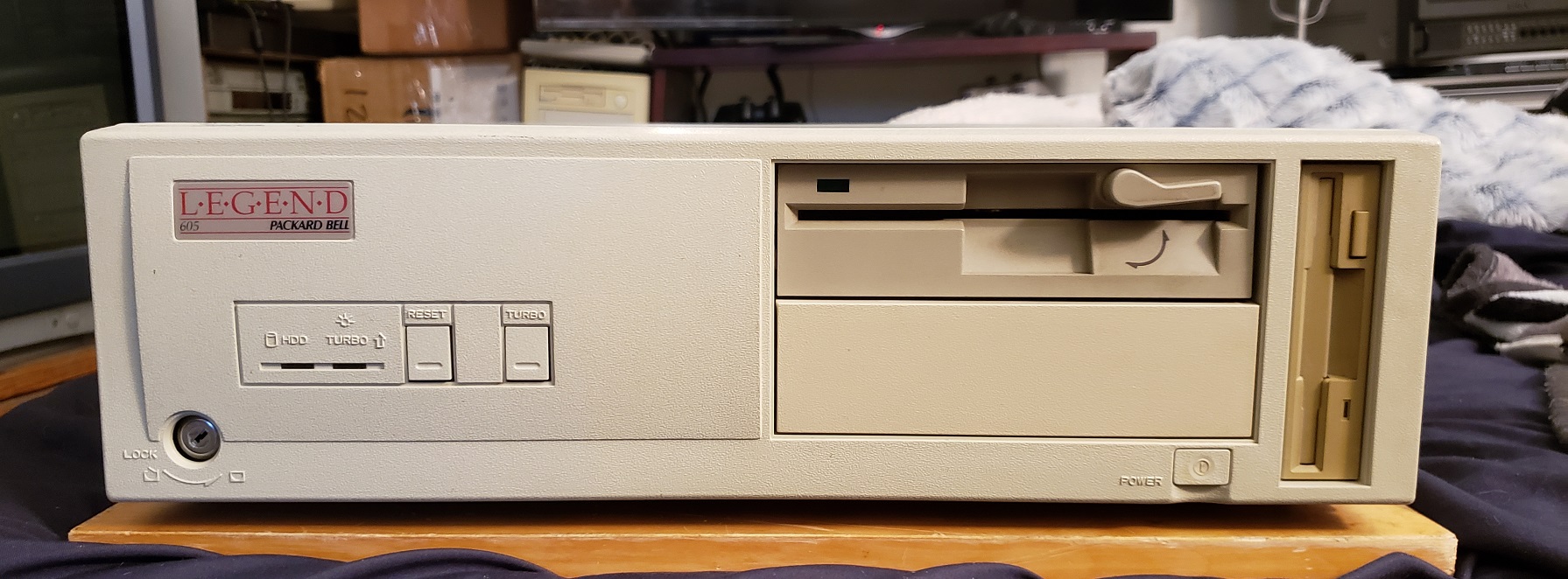
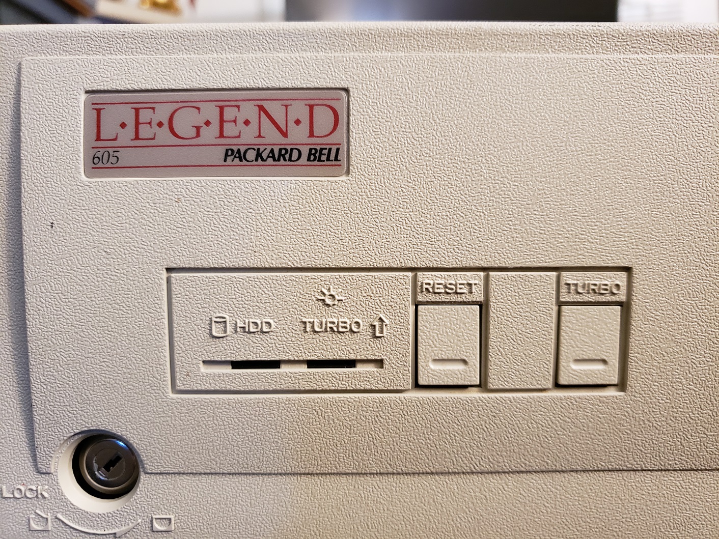
The Legend 605 is a fairly small and compact desktop machine. On the left of the case, we have a keylock as well as LEDs for HDD activity and power/turbo. Next to the LEDs are two buttons for reset as well as an actual turbo button. The buttons are more like loose plastic cut on three sides that when pressed bend inward and press on a real button.
On the right side of the front of this case, we have dual 5.25 inch bays and a single 3.5 inch bay in the vertical position. For a small 486 class PC, this is perfect as it gives you room for two floppy drives, 1.44MB as well as a 1.2MB 5.25 inch drive as well as leaving a single 5.25 inch bay open for a CD-ROM drive if you wish.
Below the bottom 5.25 inch bay is the power button which is connected to a long plastic rod that physically switches on the power.
On the left of the rear of the case, we have standard power connectors. To the right, the Legend 605 has four expansion slots in a horizontal configuration and several built-in I/O below.
From left to right we have a serial port, parallel port, and thirdly a gameport for attaching a joystick or something like a Gravis Gamepad. Usually, these are included in conjunction with some form of built-in audio but the 605 offers no audio abilities. Next to the gameport is a standard VGA port followed by dual PS/2 ports for keyboard and mouse, a nice addition to find on any 486 class PC.
The cover is removed by removing two screws in the rear of the case and sliding the case top forward.
A sticker with jumper settings and board layout should be on the inside of the top cover but I’ve added it here for reference.
case open with cards and HDD bay removed.
In the image above the HDD caddy is already removed but a metal caddy that holds the hard drive fastens onto the dual 5.25 inch bays and can hold a hard drive in a vertical position.
My machine came to me with a 425MB WD HDD loaded with DOS 6.22.
clear view of motherboard
1 ) CPU – The 25MHz 486SX seemed to be the go-to CPU for lower end OEM PCs. The 25MHz 486SX lacks a math coprocessor and does fall at the lower end of the 80486 power spectrum running on a 25MHz front side bus. The CPU on the Legend 605 is soldered to the motherboard. Thankfully the Legend 605 does offer a fairly good upgrade path for CPUs.
2) CPU upgrade socket – fortunately the 605 does have a secondary “upgrade” CPU socket to allow for relatively easily upgrades to your CPU. Unfortunately, this socket is a LIF (low insertion force) socket as opposed to a ZIF socket which has a lever mechanism to assist in easily swapping CPUs. Installing a CPU in this socket is fairly easy but without the correct tools, it can be tricky to remove.
The upgrade socket can support a wide array of 5 volt 486 class CPUs such as the 66MHz DX2 which will give your PC a very noticeable boost in performance. Installing a new CPU and then jumpering jumper JCPUP (as well as adjusting for front side bus if applicable) will let the PC know a CPU is installed in the upgrade socket and deactivate the soldered on 486-25 SX while enabling the CPU installed in the upgrade socket. My machine has been upgraded with an Overdrive chip. The overdrive chip has a built-in voltage regulator and runs with a x3 multiplier on a 33MHz bus giving it a speed of 100MHz. This is a huge speed upgrade over the CPU the Legend 605 comes stock with. Note that the Legend 605 does not seem to support the Pentium Overdrive CPU.
3) L2 Cache – The Legend 605 supports 64k, 128k, and 256k of L2 cache memory on the motherboard. Mine has been upgraded to the full 256k of L2 cache. Anything over 256k of cache on a 486 class PC usually results in small speed increases with diminishing returns so having 256k on this board is a good amount and I’d say is the general standard for a machine like this one.
4 ) RAM – The memory configuration on the Legend 605 is slightly unusual as it has a maximum memory amount of 20MB with 4MB of memory being soldered onto the motherboard. You can upgrade to a full 20MB by adding four 4MB memory sticks as I have. In my experience with PCs of this age, usually there is no memory soldered onto the board and usually, they at least allow up to 32MB maximum.
5 ) Video – The built-in video chip is from Oak Technologies and uses the OTI077 VGA chip. There is 512K of VRAM soldered onto the board with empty sockets next to these allowing for upgrading to a full 1MB of VRAM. The video on the Legend 605 is supposedly on the VLB bus and not ISA but I haven’t been able to verify this.
I don’t have much experience with Oak Technologies but from my research, they seem to be pretty middle-of-the-road type chips offering mediocre to adequate video but nothing extraordinary.
6 ) Riser Connector – slot for the riser card which has four 16-bit ISA slots for expansion cards.
7) Floppy connector and single built-in IDE connector for supporting two IDE devices
8) AT power connector (note the battery in the image below is a replacement, the old battery was removed and a new one soldered in its place by the previous owner)
The Packard Bell Legend 605 has the potential to make a really nice retro DOS or Win 3.1 build. In its stock configuration with the 25MHz 486SX it is a bit on the weak side for a 486 but it can easily be made to be as powerful as a 486 as you want with the CPU upgrade slot. adding an Overdrive CPU or even a AMD 5×86 at 133MHz makes quite a powerful machine. Although most later 486 PCs can accept at least 32MB of memory the 20MB limit shouldn’t be much of a hindrance as many games did not require such a large amount. Adding a fast ISA video card and a sound card along with a CPU upgrade makes the Legend 605 a quite capable machine.
The legendary Abit BP6, released in 1999 was the first dual-processor socket PPGA 370 motherboard and the first board to finally bring multi-processor boards at an affordable price to the consumer market. There were motherboards prior to the BP6 which featured more than one CPU on the board. Slot 1, Pentium Pro and even so far back as the 386 motherboards were available that could support multiple physical CPUs on board in what was known as SMP processing. Generally these setups were found in very high end and very expensive workstations and were more or less out of reach to the average consumer.
In 1998 the Mendocino Celeron CPUs were released which were intended to be Intel’s low cost alternative to the Pentium II and eventually the Pentium III. One interesting thing about these CPU’s was that they were released as SMP (Symmetric Processing) capable meaning that two Mendocino Celerons could be made to theoretically function together on a single motherboard. It doesn’t seem Intel intended consumers to find out about this function but regardless it was discovered and soon Abit decided to take advantage of this fact by releasing the SMP capable Abit BP6. It was soon found that users could, with the right operating system and with certain games that supported SMP get better performance at a lesser price with dual Celerons on the BP6 than with a single more expensive CPU. With that bit of history out of the way let’s take a closer look at the motherboard itself.
The Abit BP6 uses the Intel 440BX chipset and ONLY supports Mendocino Celeron CPUs. Users have had success upgrading to later CPU’s such as Coppermine Pentium IIIs and even reportedly Tualatin Celerons via adaptors such as the Neo s370 Powerleap adapter and various modifications. Only the Mendocino Celerons are confirmed to work in dual processor AKA SMP mode though there are many posts of uses getting later Coppermine and Tualatin CPUs working in these modes as well with adaptors and modifications. The BIOS on the BP6 has quite a bit of overclocking and tweaking features and allows for setting the CPU multiplier and front side bus via BIOS settings. default front side bus for the Mendocino Celerons is 66MHz but the board does allow for settings of 75MHz as well as 100MHz FSB and above via a very user friendly “Soft CPU II” option in BIOS.
Built in I/O on the board is pretty minimal with dual PS/2 for mouse and keyboard, dual USB 1.1, a parallel and dual serial ports.
1) CPU – The BP6 only officially supports the Mendocino Celeron from speeds of 300MHz up to the fastest released chip of 533MHz (with the newest BIOS version installed). Despite being budget CPUs the Mendocino Celerons were very competitive with Intels higher end Pentium offerings. My board with the latest BIOS update features dual 533MHz Celerons which are very capable of playing most any Win 9x era games as well as early XP games provided you lower some settings. With a decent heatsink and thermal paste it’s not hard to overclock to 600MHz but this is about the maximum you’ll get out of the Mendocino while maintaining any stability.
Be aware this board only functions in SMP (dual CPU) mode with operating systems and software that allow it. Even though operating systems such as MS-DOS and Windows 9x do not support dual processors these systems will happily run on this board in single CPU mode and dual booting OSes is always an option.
2) RAM – The BP6 features three memory sockets for installing up to 768MB of SDRAM of either the PC66 or PC100 variety. PC133 memory will work fine but it will downclock to PC100 speeds. Each slot will also only accept up to 256MB DIMMS with larger sticks only being detected as 256MB.
3) AGP – The AGP slot is a x2 slot 3.3v slot. You can safely use anything up to about a Radeon 9700 Pro or Geforce 4 though the AGP x2 is going to bottleneck the power these video cards could potentially provide.
4) Five PCI v2.1 and two 16-bit ISA slots
5) Floppy and IDE connectors – One standard floppy connector and two ATA 33 connectors supporting two devices each for a total of four IDE devices.
6) HighPoint HPT366 – This additional controller chip supports four extra IDE devices via the white connectors at ATA 66 speeds, double the speed of the two standard connectors. Together that means the BP6 can support up to eight IDE devices in total.
7) SB Link – The BP6 sports a Sound Blaster link connection. the purpose of this cable was to create better sound compatibility for PCI sound cards when operating in a DOS environment. Unfortunately, the connector is somewhat uncommon on PCI sound cards and Creative themselves only made one card, the AWE64 PCI that even supported the cable. The SB Link connector is made somewhat even more redundant since the board already supports two 16-bit ISA slots.
Now that we’ve taken a look at the motherboard itself let’s take a look at the PC I built around it.
Since the BP6 is kind of a “poor man’s workstation” I decided to go with this server style case. The case itself is quite tall with a 3 digit LED display as well as a panel that slides down to reveal five 5 1/4 drive bays and two 3 1/2 bays.
Here is a look at the rear as well as the side of the case.
And the three digit LED MHz display.
Here is a look at my Abit BP6 under the hood.
I used some quality thermal paste and cooler master heatsink/fans on my CPU’s as well as attached a small fan to the heatsink on the chipset to help with any overclocking I decided to do. I was able to overclock this particular board to 600MHz by raising my FSB to 75MHz but anything higher resulted in non posting or instability.
I am using the full 768MB of PC100 RAM as well as running the Windows 2000 operating system. Windows 9x does not support SMP processing AKA dual CPUs so my pre W2K OS choices were rather limited, especially if gaming is your priority. I went with W2K over XP simply because it is a bit of a lighter OS compared to XP as far as requirements go and should run a little better on this setup as well as allowing me to play all the games I’m looking to play. Be sure to upgrade to the latest W2K service pack if you go with this OS for your build as some games such as Quake III failed to run for me before updating.
My hard drive selection was a simple 40GB Western Digital IDE drive from around the early 2000’s. nothing spectacular but more than enough for this setup.
Let’s take a quick look at the two expansion cards I have added to this board.
For sound I went with the venerable Sound Blaster Live! although this motherboard does have two 16-bit ISA slots DOS was not the focus of this build since DOS can take not take advantage of the dual CPUs. The SB Live! cards are good all around Windows 9x and early XP cards that support EAX and even have decent DOS support for being PCI cards. I could have gone with a later Audigy card but I felt this was a great card for the time frame I was going with.
My initial choice for a video card was the Matrox G400 MAX which is a capable and IMO underrated card for gaming that also matched the workstation theme I was going with for this build. Unfortunately, even though its performance was good I wanted something a little more powerful and switched to a Geforce ti4600 though I found much of the power of that card wasted on the AGP x2 slot and weaker processors. I finally decided to try out the Geforce MX 400 which is roughly equivalent to the Geforce 256 in power and gave me framerates well below the Geforce ti4600 in some cases and noticeably better than the G400 MAX. This card just kind of “felt right” for me and what I was looking for from this build but your choice may differ.
I don’t know if I’ll keep this video card but I may try out the Geforce 2 Ultra or the PowerVR Kyro II in the future for this PC.
The Abit BP6 was in many ways ahead of its time as an affordable consumer level board. The main problem I have with the board is that it came out at a time when SMP processing was a niche area reserved for specific work tasks. The problem was that no mainstream OS supported the dual CPU configuration and while most users at the time were running Windows 95 or 98 only Windows NT, Linux and a few other less popular operating systems supported more than one CPU. When Windows 2000 and then XP were released this largely solved this problem as Windows XP quickly became a popular OS for home PCs and it supported dual CPUs. The other problem was software, specifically games. There was not a lot of dual CPU support written for games pre 2000 and even for a time after. Quake III is perhaps the best example of a game supporting dual CPUs but even though it did receive a noticeable FPS boost in dual CPU mode the mode could be glitchy on some setups. There were other games such as Falcon 4.0 but other than a few titles here and there users of the BP6 were stuck in single CPU mode. By the time dual CPU support and things like multi-core support were becoming more widely supported the Mendocino Celerons, even at 533 or 600MHz were woefully underpowered or lacked the code to run these games. Quake 4 from 2005 is another relatively early example of a dual CPU supporting game but the Mendocino CPU is incapable of running it at all due to lacking SSE code in the CPU.
In short the BP6 is a nice motherboard, even in single CPU mode. It was a pioneer in the consumer market but unfortunately, the whole gimmick of the dual CPU support was largely lost on the lack of software, specifically games, that supported it. In this sense as a gaming motherboard I couldn’t recommend the BP6 as there are better single CPU options available for early 2000s retro PC gaming that are more powerful and easier to find. As a cheaper workstation build of the time the board performs well and if your a collector of vintage hardware it’s a fun board to have and play around with.
The IBM 300XL is a late 90’s PC from IBM that may look quite familiar to some of you. It uses the same case as the IBM PC 350 we covered on this blog way back in distant 2018. My first question is why did IBM use a model number that is lower than a previous model even though it uses a more advanced slot 1 motherboard as opposed to the socket 7 board in the PC 300. I guess that’s where the XL comes into the name, anyways….
On my 300XL if you look in the lower left hand corner my case is missing the cover for some unused ports. I’m guessing some models had audio jacks in this position. A little to the right of the center is the large beige power button and to the right of that is the sliding cover that when slid to the left reveals the drive bays. I have to say I do like the “Y2K Ready” sticker placed under the IBM logo.
Guess someone forgot to remove it.
Sliding the panel to the left reveals a single 3 1/2 bay and two 5 1/4 bays as well as one peculiar slim bay in the upper left corner I believe was reserved for a PCMCIA slot though there doesn’t seem to be an easy way to mount anything in this slot on my PC. My PC has a pretty standard combo of a 1.44MB floppy drive along with a CD-ROM drive.
Flipping the 300XL around reveals the ports on the back. There are five total expansion slots with four on the right and a single slot on the left coming off a riser card. At the center of the case we have two ports, a serial port and an IR port.
At the bottom of the case from left to right we have a number of jacks. Firstly are dual 3.5mm jacks for audio in and audio out for the built in sound. Next to this we have dual PS/2 ports for the keyboard and mouse followed by the parallel printer port. Next, we have dual USB jacks though it’s unclear if these are USB 1.0 or 1.1 as the user manual does not specify they are very likely 1.0. Lastly, we have an Ethernet port followed by a standard 15-pin VGA connector for the built in video.
The case of the 300XL is a screwless design and should come off by depressing the tab to the rear and pulling the upper casing off. On the underside of the case top should be a diagram of the motherboard along with jumper settings.
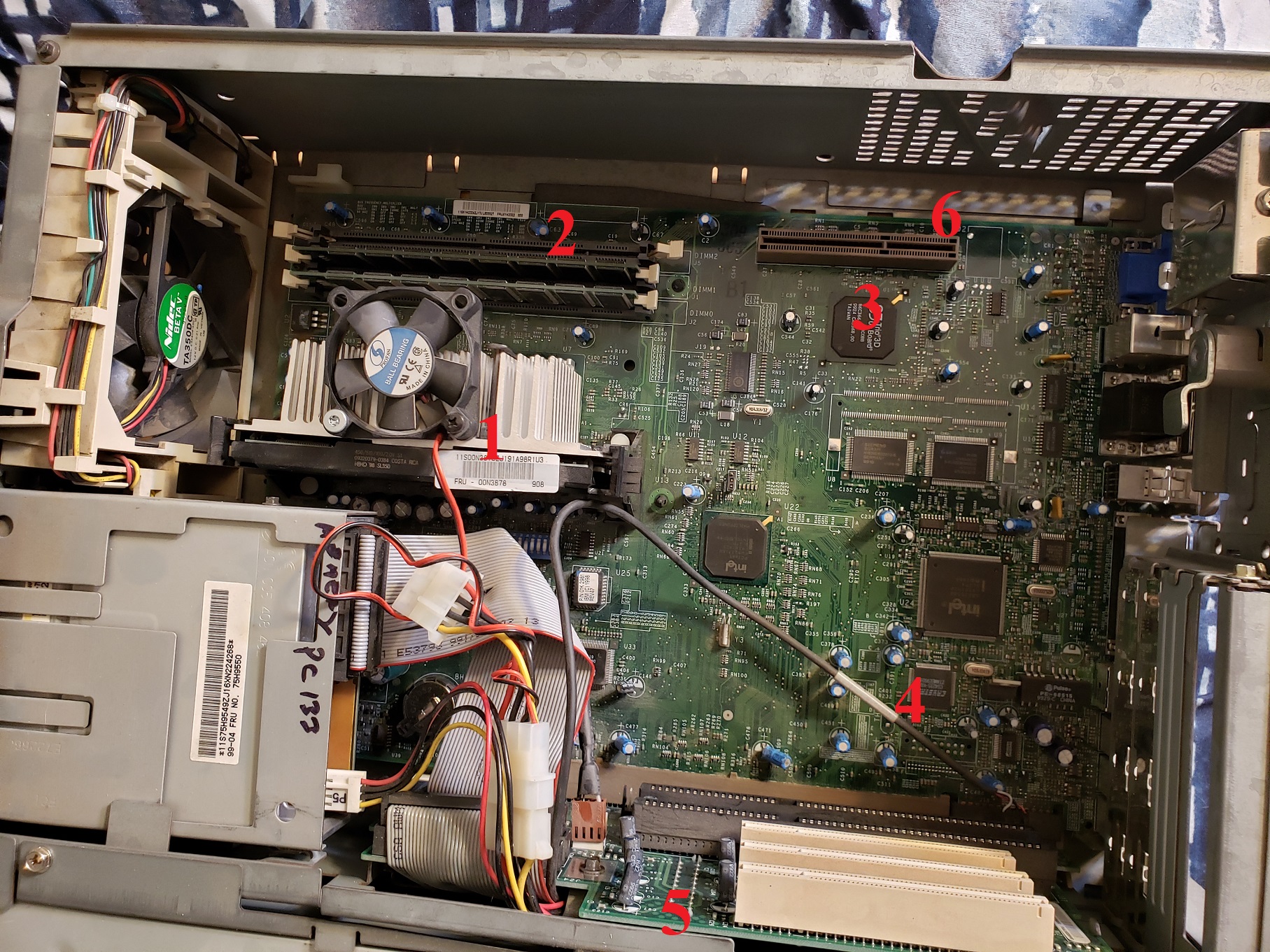
Here is my IBM 300XL with the case removed.
At about the center next to the CD and floppy drives is a mount for two hard drives. mine came with dual IDE HDDs one being 8GB and the other 2GB. Originally as I received it this PC had Windows NT installed but I did reformat the drive and installed Windows 95 OSR B. The power supply appears to be a fairly standard AT supply but features two extra power connectors that connect to the mainboard right behind the AT connector and another to the riser card.
Above we have the motherboard exposed with the riser card and mid support bar/HDD bays out of the way. The board is a proprietary board using the Intel 82440FX chipset. The board does provide sound in the form of a Crystal CS4236 chip providing sound blaster, sound blaster pro and WSS support though I was unable to locate any obvious crystal sound chip on the motherboard.
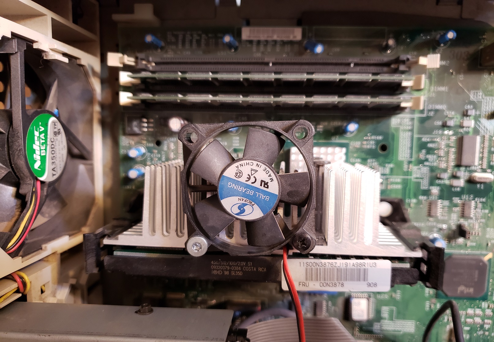
1 ) CPU – My 300XL came with a 233MHz Pentium II slot 1 CPU but also has jumper settings for installing a 266MHz Pentium II. The 300XL was probably a pretty early adaptor of slot 1 and although I havn’t tested this the 300MHz “Klamath” Pentium II would likely work as well. Later “Deschutes” Pentium II’s operate at a lower voltage which the 300XL does not appear to provide. Also Pentium II’s from 350MHz up also run on a 100MHz FSB which the 300XL also does not appear to be able to provide though provided voltage is not an issue could operate at a lower FSB and thus lower speed. The 233MHz PII is the slowest of the Pentium II’s but it should still make a capable CPU for most all DOS titles and early Windows 9x games. The CPU in my machine appears to get its cooling from a shroud directing air over the heatsink from a case fan.
2 ) RAM – The PC 300XL supports up to a maximum of 384MB of 168 pin DRAM memory. My 300XL currently has 96MB of memory installed. I’ve found many IBM PCs such as this one to be very picky about memory and none of my spare memory sticks worked on the 300XL even though they physically fit into the board. The manual states these specific memory requirements.
Must be 168-pin, unbuffered, +3 V type Must have gold-lead tabs Must have 60 nanosecond (ns) access speeds only Must have a height of no more than 3.05 cm (1.2 in.)
3 ) Video – Built in video for the 300XL is provided by the S3 Trio64V2/DX and 2MB of DRAM. This chip is one of the later of the S3 Trio2D graphics chips. This makes an excellent video chip for 2D games and features top notch compatibility for DOS titles but lacks any 3D support. The chip does make sense considering the 300XL’s main purpose as a office or home work PC.
4 ) Riser – The 300XL uses a riser card to interface with any added expansion cards. The card features five 16-bit ISA slots (one on the oppose side) and three PCI slots though the PCI slots are shared with ISA for a total of five possible expansion cards.
The 300XL does not feature any AGP slot but something like a PCI Voodoo 3 2000 card as well as a good ISA sound card would be mostly all that’s need to turn this PC into a very capable DOS PC and even a quite adequate Win 9x gaming PC.
5) Piezo speaker.
The 300XL is basically a more powerful IBM PC 350 in the same case. The 2D video is slightly upgraded and it features the exact same amount and type of expansion slots so I’ll be a bit lazy here and quote what I said about that machine as it mostly applies here as well.
“The IBM PC 350 makes a fair retro computer. It excels at DOS retro gaming and needs very little besides an ISA sound card to have a very compatible machine. As a Windows PC it is quite acceptable and a PCI 3D accelerator card such as a Voodoo would do wonders. The BIOS tends to be fussy though and when I made ANY changes including simply unplugging the mouse the machine demanded I enter the setup feature upon restarting and change/save the new settings. There are other annoyances such as the extra connection needed on the power supply as well as the slightly picky 168 pin RAM slot.
The case itself is quite nice offering a sturdy design, decent bay expansion as well as being easy to get into. I also like the sliding piece on the front so you can cover up your ugly discolored drives when not in use. Adding drives though requires some disassembly and is a hassle.”
The main difference with the 300XL is the CPU and the switch from socket 7 to slot 1. The Pentium II makes for a much more capable processor and thus a more capable computer when it comes to being a Windows 9x gaming machine though at the expense of being able to install a much slower socket 7 CPU and have a more speed appropriate DOS PC.
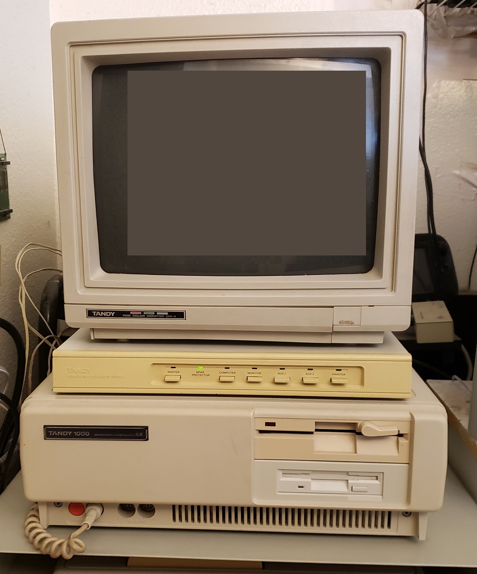
Released in 1987 the Tandy 1000 SX was an evolution of the original Tandy 1000 which itself was a clone of the IBM PCjr. The Tandy 1000 line featured several advantages over standard IBM compatibles of the time such as built-in “Tandy video” which offered CGA video modes along with 160×200 and 320×200 16 color modes. The Tandy 1000 also offered enhanced Tandy 3- voice sound. Both Tandy video and audio were very widely supported in games.
The 1000 SX is an enhanced version of the original Tandy 1000 offering many improvements that more or less correct every issue that the original Tandy 1000 had such as making upgrading and expanding the PC easier and adding a faster CPU “turbo mode” as well as a DMA controller to speed up certain processes. Many retro PC enthusiasts consider the Tandy 1000 SX one of if not the best bang for your buck IBM compatibles of the 1980s.
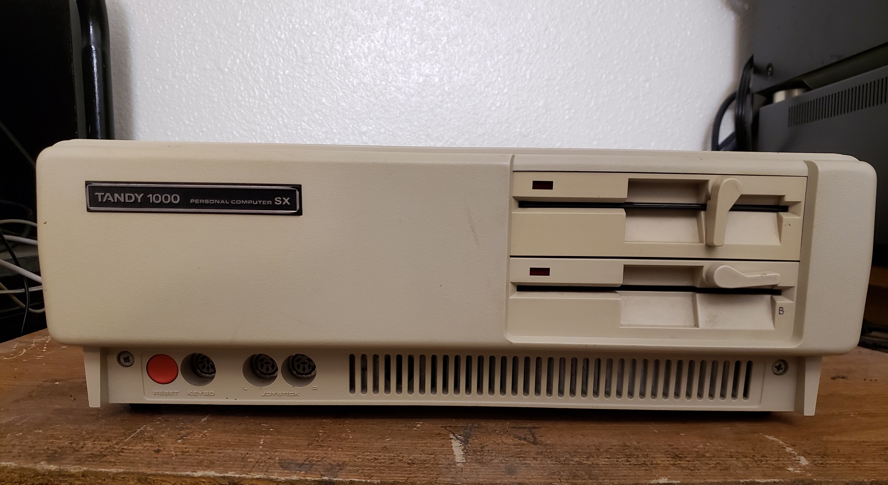
The 1000 SX case when compared to a IBM PC is noticeably smaller which saves desk space. It’s also mostly made of plastic which also makes it a significantly lighter PC. The SX came stock with dual 360k 5 1/4 floppy drives in its dual 5 1/4 bays though the built-in floppy controller also supports 720k drives. We will detail the process of upgrading to one of these larger capacity drives later in the article.
At the bottom of the front of the case there are two screws on the far left and right. Removing these is all that is necessary for removing the cover. On the bottom left of the front we have a large red reset button. Next to this we have a keyboard port. The Tandy 1000 SX uses a proprietary style keyboard port like most of the early Tandy 1000 line. This port is not compatible with standard IBM type PC/XT/AT keyboards so a Tandy keyboard is required though there are modern adaptors that allow the use of standard PS/2 keyboards.
To the right of the keyboard port are dual round 6-pin joystick ports. These joystick ports are also proprietary and require joysticks compatible with the Tandy 1000 and Tandy color computer line.
Turning the Tandy 1000 SX around and we can see the various rear connectors. The power switch like the one on the IBM PC/XT/AT is on the rear left side though the switch itself is not visible in this image. Starting from left to right we have a standard 3 prong connector for the power cord. Next is a card edge style connector located directly under the model label. This is actually an edge-style parallel port and is intended to be used with specific Tandy printers. Adaptors were made to connect non-Tandy parallel port devices to the edge connector. Next is the seldom if ever used DE-9 lightpen connector followed by the built-in video and audio jacks.
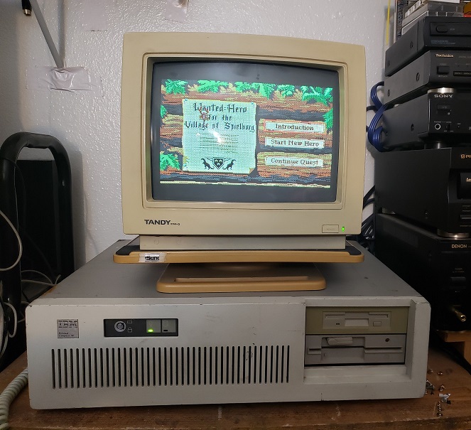
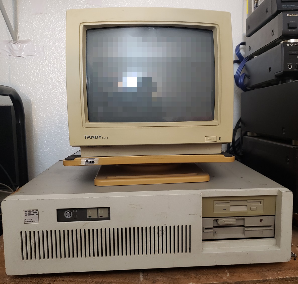
First up is a standard DE-9 connector for connecting to TTL RGB monitors. Tandy made several Tandy specific monitors of differing quality like the CM-5 that I’m using and the higher quality CM-11 but any standard CGA type monitor will work. The video output of the Tandy 1000 SX is based on the video capabilities of the failed PCjr but since the PCjr failed this video standard became known as TGA or Tandy Graphics Adaptor. The Tandy 1000 SX can output standard CGA as well as the TGA modes which allow 16 colors on screen at one time. This more or less resembles the look of EGA in low resolutions though they are not the same.
Tandy playing EOB in CGA modeTandy playing EOB in TGA 16 color mode
CGA compatibility on the Tandy 1000 line is almost 100% and is CGA register compatible though due to slight differences in text characters used very few games (ex. ICON : Quest for the Ring and The Seven Spirits of RA) may show some minor graphical issues. As for the extended TGA modes available the Tandy 1000 also supports 160×200 with 16 colors, 320×200 with 16 colors and 640×200 with 4 colors out of the palette of 16 colors. A very significant number of games do support Tandy 16 color graphics. Some of these games allow the user to choose the color mode between CGA and TGA but some games will automatically detect if a Tandy is present and force 16 color TGA mode. Some games such as ArcticFox only support 16 color mode via the Tandy graphics adapter.
Next up we have the RCA style A/V jacks for video and audio. At first glance it looks like stereo audio jacks but the red jack is for color composite out for connecting usually to a TV but also to some monitors. Some games may also show differences in colors when displayed in color composite mode on a Tandy 1000 as opposed to an IBM compatible CGA card.
The audio out is very useful if you don’t want to output sound through the internal speaker and instead wish to use an external speaker. The audio out though is disabled by default and some games may fail to initialize. there is a program called tdyspkr.com which should allow you to select the A/V audio jack as active on boot up for those programs which fail to see it.
Since we are talking about sound It’s worth mentioning the Tandy 1000 SX “Tandy sound” which is a bit more advanced than the standard PC speaker and uses 3 voice channels and 1 sound channel is a clone of the PCjr sound. Tandy sound or Tandy 3-voice sound as it’s also known is generated by either a SN76496 or NCR8496 Chip. Some games such as Thexder only support PC speaker or Tandy speaker sound with Tandy sound being noticeably superior and less grating on the ears. If you opt to not use external speakers Tandy 1000 SX also sports a nice sounding large cone speaker at the front of the case
Removing the case to get inside is relatively easy and only requires removing two screws located on the front face of the case.
Image was taken before math co-processor and memory upgrade
The only expansion card for my Tandy 1000 SX is an I/O card for a serial and parallel port and this is the only card that was installed in this machine when I received it. The metal bar going across the motherboard from the side to the dual 5 1/4 bays is actually a support beam that is easily removed. Its purpose is to help support a monitor if one is placed on top of the case as was a common practice of the time.
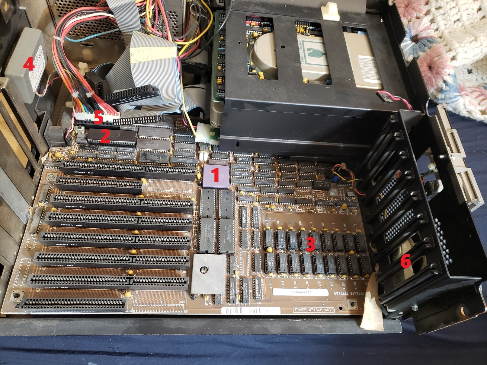
Removing the dual 360k 5 1/4 floppy drives gives us a better view of the motherboard.
Like the original IBM PC the 1000 SX only has 5 8-bit ISA slots. Unlike the IBM PC though, the Tandy 1000 SX has the floppy drive controller as well as the video built-in. The motherboard of the 1000 SX also has a built-in DMA chip to speed up certain processes, something the earlier Tandy 1000, 1000A and 1000 HD lacked.
1) CPU – The 1000 SX uses an 8088 like previous models although the SX runs default at 7.16MHz with the ability to downclock to 4.77MHz for compatibility with older software. The SX has no turbo button so to slow the CPU back down to 4.77MHz you need to use the DOS commands “MODE SLOW” and “MODE FAST” in order to switch speeds. The default speed is 7.16MHz though at boot up you can also press the F4 key on the keyboard to boot into 4.77MHz slow mode. The MODE command which sets the CPU speed is only available in the OEM version of Tandy DOS 3.x.
2) Math Co-Processor – The SX does have a socket next to the CPU for adding a math co-pro. I elected to add an 8MHz capable 8087-2. Adding a math co-pro is hardly necessary and only a handful of programs and games from the time can take advantage of it.
Next to the CPU is a small switch box. These switches can be used to disable several features mostly for the purpose of adding discrete cards. All switches are set to “on” by default. switch 1 disables the built-in video. Switch 2 controls the IRQ the built-in video uses. Switch 3 disables/enables the internal floppy controller and lastly switch 4 will enable/disable the parallel port.
3) RAM – By default the 1000 SX came with 384k of memory but is easily upgradable to a full 640k of memory. My 1000 SX only came with the original 384k of memory but I upgraded to the full 640k via eight 256k x 1 150ns (or faster) DRAM chips. After adding the additional memory jumpers E1 and E2 also need to be removed for the system to detect the change.
640k should be enough memory for any game that will run well on the SX and there is even evidence that expanding past 640k on a 1000 series can cause issues and incompatibilities with games.
4) System ROM BIOS / Smartwatch Battery – This socket is used for both the system BIOS chip on the SX as well as the battery which holds time for the system clock.
System ROM BIOS
you’ll notice that on my machine the BIOS chip is in a socket that is a little high. that’s because my SX has a separate battery module in between the motherboard socket and the BIOS ROM. I don’t believe all SX’s have this module but mine does. its purpose is to hold the date which needs to be entered every time Tandy DOS 3.x loads up on boot. To access the battery you have to first remove the ROM chip which is socketed over it.
You can still purchase a modern replacement for this battery HERE which allows the use of a coin-style battery.
5) Speaker Volume control – Unfortunately there is no way to control the volume of the speaker from outside of the case but Tandy did include a volume adjustment on the motherboard. If turned down all the way the speaker can be completely muted.
6) floppy connector – Built-in connector for connecting floppy disk drives to the SX. The built-in controller supports both 360k 5 1/4 disk drives as well as 720k 3 1/2 style disk drives.
7) Tandy sound chip – As mentioned earlier the Tandy 3-voice sound is generated by either an SN76496 or NCR8496 Chip. For the Tandy 1000 SX it can be either chip. My SX uses the NCR8496 which is a clone of the original Texas Instruments SN76496 chip.
It is almost a perfect clone though there are slight audible differences in the noise channel. I suppose since it’s socketed an original SN76496 could be sourced and swapped out with the clone chip. If you are interested more information on the sound chips can be found HERE.
UPGRADES
There are common upgrades that apply to most all PC and XT machines such as an NEC V20 for a small speed boost or XT-IDE adaptor. There isn’t any place to really mount a hard drive and I use a XT-IDE compact flash adaptor myself which works well. I am using a 32MB card with Tandy DOS 3.2 installed but DOS 6.22 with a larger CF card works just as well.
A hardcard or hard drive on an ISA a card would be a more period correct, though slower option.
I don’t recommend adding an EGA or VGA video card to the SX though you certainly can I just find the whole point to using a machine like this is to take advantage of the Tandy sound and video that so many games supported.
A serial card or bus mouse card could also be useful if you are planning on using a mouse with your Tandy.
I did however add a Sound Blaster 1.5 w/ CMS chips. I’ll be using this machining mostly for older titles that support PC speaker or Tandy sound only though I wanted the option for games that do support digital sound and or adlib/CMS sound.
The upgrade I would definitely recommend is replacing one of the 360k 5 1/4 floppy drives with a 720k 3 1/2 drive. I replaced my drive B with a 720k drive as opposed to drive A since the primary format of the time was 360k disks and thus many “booter” type games came in that format which may require being read from drive A. Since there are no 3 1/2 size bays on the SX case you will need a 5 1/4 to 3 1/2 bay adaptor. Keep in mind you can press the F3 key on bootup to swap the A and B drives.
Some things to consider when adding a 720k drive is that the cable the SX uses is very short and also uses edge connectors so it’s very likely you will need some kind of adaptor and or extension to reach for the floppy drive or you’ll need to use a different cable altogether.
Original 1000 SX floppy cable.
Another thing to keep in mind is the Tandy 1000 SX uses floppy cables without a twist in them so you will need a 720k floppy drive with jumpers that allow you to designate what drive it is.
D0 designates the drive as drive A while setting the jumper to D1 sets the drive as the B drive.
If you can’t find an adaptor and or extension which allows you to use the original short floppy cable that came with the Tandy 1000 SX you will either need to find a longer floppy drive cable without the twist or modify a more common “twisted” floppy cable by untwisting the cable as seen below.
Unfortunately, I had no luck getting my modified cable to work though I know others have. I did end up finding an edge connector adaptor that also had an extension cable attached to it which allowed me to use the original cable that came with my SX and everything works fine.
So is the Tandy 1000 SX a great computer for 80’s PC gaming? I’d say so and I would at the very least say it was one of if not the best value for the money at the time. The built-in Tandy sound and video were far superior to PC speaker and CGA common at the time and many, many games supported the standard. There are a number of games that are just best experienced with Tandy color and or sound. You could have bought an EGA card but those would have been quite expensive and sound cards weren’t really supported until the late ’80s. The option to run the CPU at both 7.16MHz and 4.77MHz for compatibility is also a nice bonus. The 1000 SX is also lighter and takes up a little less desktop space than comparable IBM models and as mentioned at the beginning of the article the SX fixes most of the issues that hampered the original Tandy 1000. I like the Tandy 1000 SX so much I’ve actually replaced my primary 8088 based XT PC with it despite that machine still holding a few advantages over the Tandy.
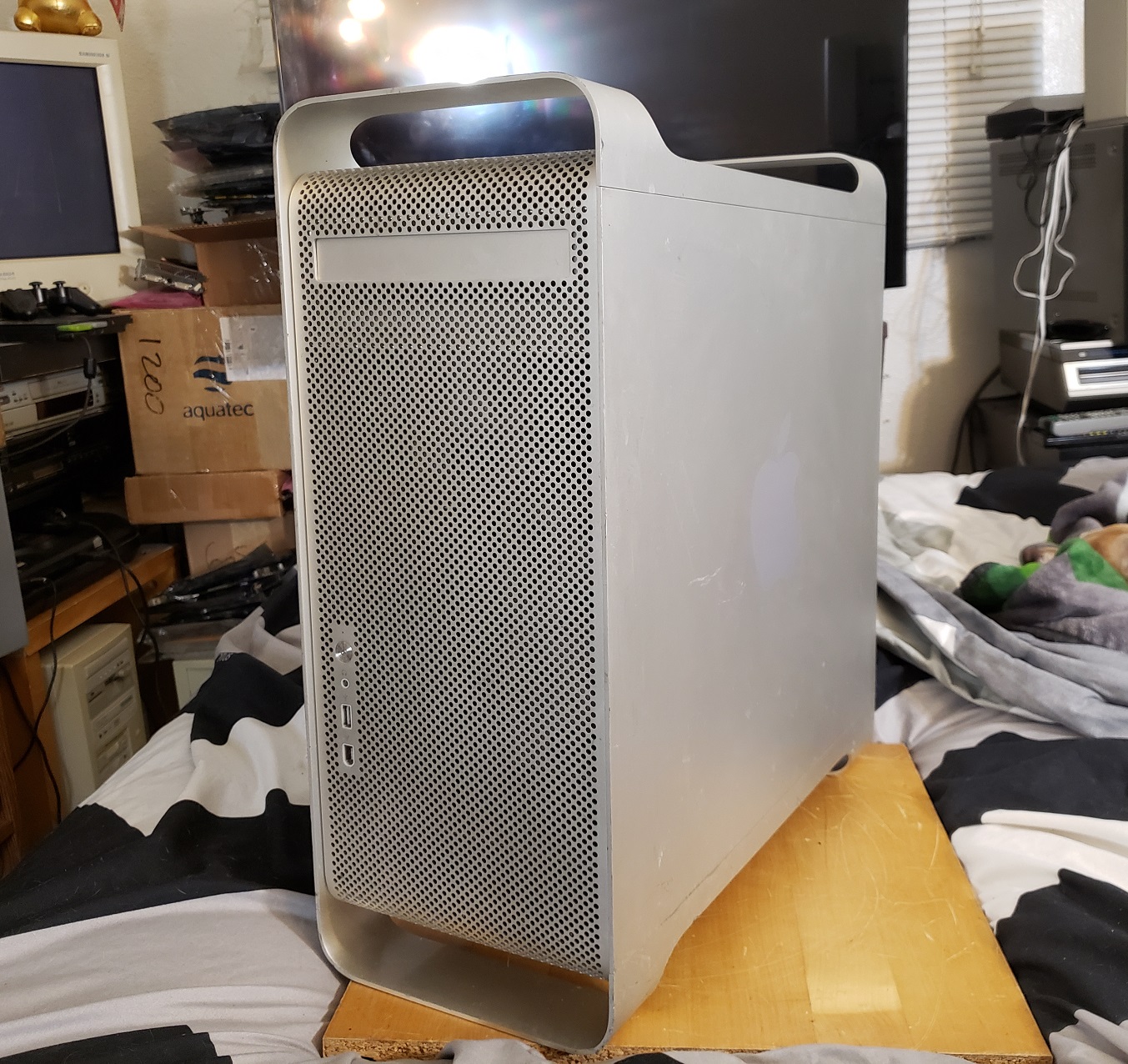
The Power Macintosh G5 series was the end of an era for Apple and the Macintosh. It was one of the last Macs to use the venerable Power PC CPU before moving onto Intel CPU’s which in my opinion made Macs little more then PCs with a custom Apple OS and took away much of their uniqueness for better or worse. The quad core G5 Macintosh was one of the last of the G5 Macs and one of the most powerful. Before we get into the specs keep in mind that older G5 Machines will have differing configurations and this is only a look at one of the last PCs in this line and not a general overview of the entire G5 line..
I’ve frequently seen these cases referred to as “cheese grater” cases due to the front. The case is all aluminum and despite the lighter weight of the metal the thing is very heavy. Being aluminum though it’s likely the case will survive long after all of us are dead, that is unless they all get melted down to make aircraft during WW III. The front of the case is very simple with a single 5 1/4 drive bay near the top for a CD/DVD optical drive and only a few inputs further down on the left.
First is the power button which does light up when pressed and powered on. Next we have a audio headphone jack and finally one USB 2.0 port and below that a Firewire 400 port. The case also has aluminum “feet” on both the bottom and top which are handy for both assisting in carrying the heavy beast of a case as well as keeping it off the ground a little. Be aware that these “feet” are very prone to being crushed if shipped improperly.
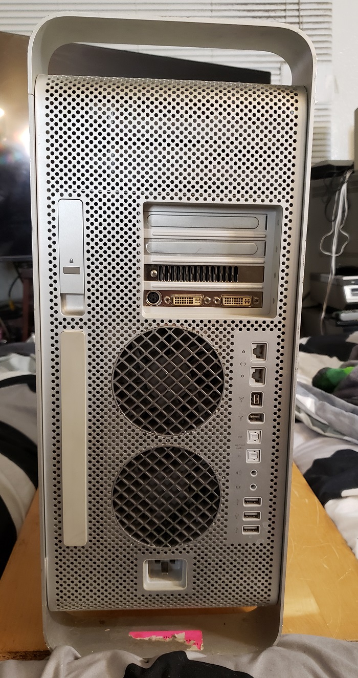
Opening the case on the G5 macs is a cinch. on the upper right hand side of the rear of the case is a simple lever. Simply pull it up and the side panel pops off. To the right of the handle are four expansion slots. Most of the rear is taken up by two massive fans and below those is the connector for your power cord.
The connector is, in classic Apple fashion, not quite your usual 3 prong connector as the shape is completely square and the three prongs are fairly flat as opposed to round so you will need a special power connector. Now the power cable used here is not proprietary but it is commonly found on high end sever equipment with high wattage power supplies. I couldn’t really say what advantage this connector type has over the more standard one and I seriously doubt it is needed for the G5 Macintosh so all it really seems to do is be extremely annoying if you happen to lack a compatible power cable and the 50 standard ones you have laying around the house won’t fit.
Starting at the top and going down the G5 has a neat row of various inputs and outputs. First are dual Ethernet ports followed by a Firewire 800 and 400 port. Next are optical audio in and out ports followed by dual 1/8 audio jacks and finally three USB 2.0 ports.
Upon removing the side panel most of the lower section of the case is further covered by a hard clear plastic cover. This is easily removed via a small handle near the top. There is also a badge on the bottom portion of the case that if you are unsure of the exact factory specifications of your model you should be able to find them there.
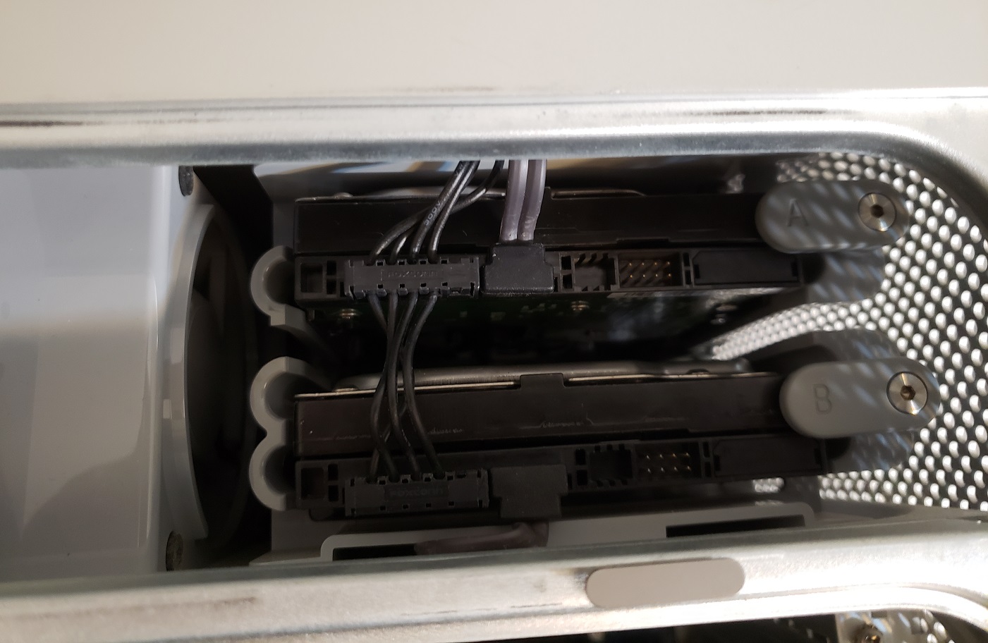
On the top left is the sole 5 1/4 drive bay which at least factory standard should be occupied with a 16x DVD drive. To the right of this bay are dual 3 1/2 drives for installing hard drives. A 250GB SATA drive was the stock drive but I have added a second drive in the lower “B” bay.
I have seen people install SDD drives in these bays but it may require an adaptor to fit securely or just be installed loose in the bay.
Below these bays are the four expansion slots.
Four slots for expansions cards is pretty anemic for a computer but in all honestly they are all PCI-e and being a Macintosh your not likely going to find you need to install much more then a video card anyways. The four PCI-e slots is actually a nice upgrade from previous models in the G5 line which lacked any PCI-e expansion slots and instead used AGP, PCI and PCI-x. Only the bottom slot is PCI-e x16 so I would suggest installing your video card in the bottom most slot. As far as I can tell there is no option to run either a crossfire or SLI configuration in the G5 Mac.
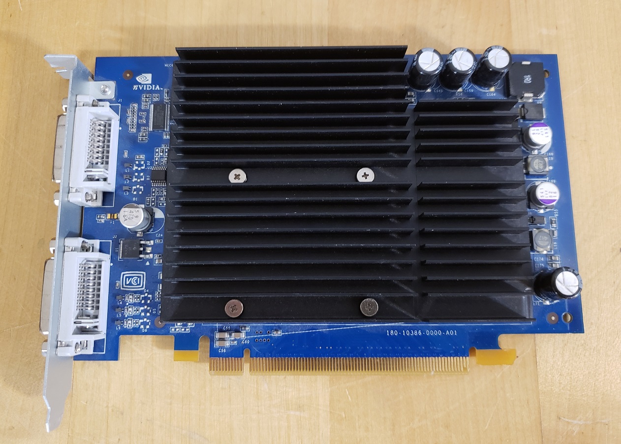
the G5 Power Mac came stock with the Macintosh version of the Geforce 6600 with 256MB or memory. This card is quite adequate though it is not the mot powerful card the G5 quad can accept and if you want to take some better advantage of what this system has to offer the video card should be one of your first upgrades if possible.
The G5 is somewhat limited on video cards it can accept due to the requirement that cards use a special Apple Mac BIOS and OS drivers. The fastest video card I could find for the G5 Mac quad was the Quadro FX 4500 with 512MB of memory. This card is basically the workstation version of the 7800 GTX and is more or less the same. Upgrading to a FX 4500 gives a noticeable boost to gaming on the G5 though finding a specific Macintosh version of the card can be difficult and/or expensive. Another route you can take is tracking down the much more common PC version of the card and flashing its BIOS to the Mac version.
You will need a specific revision of the PC card with a specific BIOS in order to flash it though. Usually the card with the L bracket on the back are flashable models but always check the BIOS revision to be sure.
Guides on the process such as the one Here can be found with a simple Google search.
Also take note the FX 4500 will require an additional power cable that connects to the motherboard and then to the card as seen below. also seen below is the connector for the IDE cable that goes to the optical drive.
The area of the motherboard below the expansion slots is dominated by the CPU and in this model, water cooling system, which is located behind the “G5” shield. To the left of this is the RAM which we can get a better look at by removing the large gray fan which simply lifts straight out.
The G5 “quad core” came factory with 512MB of DDR2 memory but I have expanded mine to a whopping 16GB of RAM. 16MB of DDR2 is a lot of memory for 2006 when the G5 line was discontinued and when many PC’s were still maxed out at 4GB with Windows XP. I do remember reading that the the jump from DDR memory in all other models of the G5 to DDR2 in the late 2005 models such as the quad core made very little to no performance improvement but I can’t seem to locate the source so I can’t confirm this though I felt it worth mentioning.
Finally we have the CPU or in the case of the Power Mac G5 Quad Core, two CPU’s.
The CPU’s and cooler are under a stylish aluminum shield with a large G5 emblazoned on it so you know what’s under it. The G5 Quad Core sports two separate dual core 2.5GHz G5 Power PC CPU’s under a factory stock water cooled system.
My machine is equipped with a liquid cooling system by Delphi. The Delphi coolers were known to have leakage issues which could corrode and destroy the system. according to Wikipedia Apple started later using a liquid cooling system from Panasonic which was much more reliable. I have found at least one comment in my research that indicated that it was actually the Panasonic cooler used in the 2.7GHz G5 Macs that was unreliable and thus resulted in the apparent scarcity of that model. This also makes sense since the 2.7GHz G5 with the Panasonic cooler seems to of been released in early 2005 where the models with the Delphi coolers were released in late 2005.
There are faster 2.7GHz G5 macs though these machines use two separate single core G5 CPU’s so they may be faster in single threaded applications and games that do not take advantage of multiple cores though the quad core is seen as the fastest overall G5 PC. Its very hard to compare speed wise with Pentium or other X86 processors but I have seen rough equivalency with faster AMD FX processors.
The Power Mac G5 quad core is the king of the G5 line and possibly of the power PC computers in general. It was the end of an era for Apple who after these machines switched over to Intel CPU’s and in my opinion lost some uniqueness. The case for the G5s is durable but be prepared because it is heavy and moving it around is a real pain. The G5s did get a reputation in its day for being fairly good machines for things like video editing but also as a space heater as it tends to give off a lot of heat while in operation. I will say my machine does get a little warm and is loud though I expect the models with fan cooling as opposed to water cooling would be even louder. It should be the king of OS X gaming though unfortunately there aren’t many games that are exclusive to power PC based OS X though .
The IBM AT also known as the IBM 5170 is IBM’s follow up to the IBM PC and IBM XT (and XT-286) home computer. Released in 1984 the 5170 featured a 286 processor and the then new 16-bit ISA expansion slots which would continue to be seen on computer motherboards all the way until the early 2000’s. The AT also supported high density floppy drives, came standard with a hard drive, featured a battery to store system settings as opposed to motherboard switches and was a great machine for then then new EGA graphics standard.
For the duration of this article please take not I will be using the terms 5170 and AT interchangeably to refer to this PC.
The IBM 5170 has a pretty utilitarian look in my opinion but there are many fans of the industrial look of this very sturdy case. My case was rescued from a garage and has some significant rust and scratching but it still fully functional. On the far left we have the standard IBM model badge as well as a lock and LEDs for power and hard drive activity.
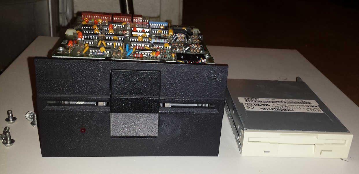
On the right side of the case are dual 5 1/4 drive bays. These bays are usually populated by two 1.2MB 5 1/4 inch floppy drives though it’s fairly common to see at least one bay housing a 3 1/2 inch floppy drive via a bay adaptor. All 5170’s support 720KB floppy drives but later revisions like mine also support 1.44MB 3 1/2 drives. I did upgrade one of my 1.2MB floppy drives to a 1.44MB drive but keep in mind you will need a bay adaptor as well as a molex to floppy power adaptor.
Below these duals bays there is also a smaller bay obscured by the front panel that could possibly mount a smaller half height form factor hard drive.
Like the earlier IBM computers the AT power switch is a large red flip switch located towards the rear of the case and on the side.
Looking at the rear we see the power supply on the left side. The AT came with a PSU of about 200w which was sufficient to power a hard drive and several expansion cards and drives. The only built in port on the AT is the AT keyboard port located next to the expansion slots. The AT like the XT supports the now standard eight expansion ports which meant now you had to sacrifice less when picking and choosing expansion cards as the earlier PC only have five expansion slots.
After the five rear screws securing the case cover are removed we can take off the top and have a look inside the AT.
As seen in the image above my original configuration included three expansion cards such as the hard drive controller as well as a serial/parallel port card and lastly a cirrus logic VGA card. The VGA card will be replaced later for something more period correct for the 5170.
Below is a view of the motherboard with the expansion cards removed.
The hard drive is housed in a bay next to the dual 5 1/4 bays. The 5170 shipped stock with an unreliable 20MB MFM hard drive though at some point my AT was upgraded to a 40MB model.
The 5170 lacks any switch blocks on the motherboard and setup is accomplished via a setup program run from a floppy disk. There is an official IBM setup program but it can be a little outdated and the setup program itself may not have options for things such as 1.44MB floppy drives even though the motherboard may be fully capable. A good alternative is a program called GSETUP which you can use with the IBM 5170 as well as other computers which require setup programs.
1 ) CPU – Early versions of the IBM 5170 used a 6MHz 80286 for it’s CPU but later revisions like the one I have pictured were upgraded to an 8MHz 80286.
Even at 8MHz the AT’s 286 processor is on the slow side as far as 286 CPU’s go. It’s certainly faster then an 8088, even at 10MHz but it’s still to slow to be optimal for many VGA titles that are more action oriented like combat flight simulators. The earlier IBM XT-286 was said to run faster with the same speed CPU due to 0 wait states though I have never personally tested this.
2 ) FPU – The 5170 motherboard does have a socket for adding a 287 math co-processor to assist in more complicated mathematical processing.
The FPU is useful for CAD type programs but it’s usefulness in games is quite limited with only a scarce few games of the time taking advantage of the processors capabilities.
3 ) RAM – All IBM AT’s came standard with 512KB of memory on the motherboard. The 5170 supports up to 16MB of memory though expanding to a full 640KB and beyond does require a memory expansion card.
4 ) Battery – The 5170 motherboard does not have any CMOS battery on the board to save settings nor switches (besides for monitor selection) thus a working battery is essential to save the settings set with the previously mentioned setup programs. The 5170 in order to save settings uses an external battery.
As original batteries are long dead for the most part buying a newer replacement will most likely be required. There are many options on eBay that use AA batteries though usually the wiring is keyed differently. Modification will most likely be required as most of these battery holders are not wired for the AT.
There is a switch between the power connector and the external battery connector. This switch is for selecting the monitor in use. The rear position is for using an MDA monitor and the forward position is for CGA. The position has no effect when using an EGA or VGA video card.
5 ) AT Power Connector
6 ) PC Speaker – The 5170 has a fairly decent PC speaker located at the front of the case.
Let’s take a look at the expansion cards I have installed in my IBM 5170 making it a late 1980’s configuration.
We will start with the two cards my PC had preinstalled and not counting the VGA card I initially installed for testing.
Hard drive controller
I believe this WD based 16-bit MFM controller card which came with my 5170 is the stock card provided for the later revision 8MHz AT’s.
The other card that came with my 5170 was a simple serial/parallel port card which is extremely useful seeing as there are no built in I/O ports.
And now to take a look at the expansion cards I decided to add.
Joystick Card
I decided to add a gameport card since my soundcard of choice did not have a gameport on it as many later sound cards do.
The card I went with was an 8-bit CH Gamecard III automatic. I didn’t have any specific reasons for choosing this card other then it’s what I had on hand although it is nice that it supports two gamepads.
RAM Expansion
Having memory over 640KB isn’t to important on an IBM AT since most games that will run acceptably on this PC only require 640KB or less of conventional memory. Unfortunately the 5170 only came with 512KB of memory stock so although that is enough to play a number of games you really want to get a full 640KB to get the best experience with the AT.
For memory expansion I installed an Intel Above Board which has a total capacity of 2MB but also allows you to backfill the conventional memory to the full 640KB bringing the total memory of the 5170 to 640KB of conventional memory and the difference allocated to being XMS or EMS memory though usually XMS is favored for 286 class PCs. Larger memory cards are available and you can even install multiple cards up to 16MB but I’ve found little use for more then 2MB in a PC of this vintage and class.
Audio
Sound cards weren’t really a thing until 1987 and most games that will run on the 5170 well won’t necessarily require anything beyond PC speaker though a sound card does expand your options. Since I decided to go more period correct with this PC I decided an original Adlib was the best choice.
The original Ablib as seen above from 1987 uses a 1/4 inch audio jack and a simple volume knob. This card uses off the shelf parts but its YM3812 FM chip is widely supported in games. These cards are quite the collectors item these days so I can’t recommend tracking one down unless you want a strict period correct machine from the later 1980’s and have large sums of cash to burn. Almost all later sound cards like the Sound Blaster 16 have perfect Adlib compatibility so I would suggest more people go down that route. There are also a number of Adlib reproductions available for a much cheaper price if you want to keep that original Adlib look. Later Adlib cards from 1990 also switched to a more commonly used 3.5mm audio jack.
Video
In the late 80’s most 5170’s would likely have been fitted with an MDA or CGA video card though the more expensive and fancier option was the official IBM EGA card allowing 16 colors on screen at once.
There are later smaller and cheaper EGA cards with all the memory built in but the official IBM card just felt right for this PC. The IBM EGA video card only comes with 64K of video memory on the card severely limiting resolutions and colors on screen and causing some games to display an incorrect image. There is a memory expansion daughterboard as seen above which brings the card up to a full 256K of video ram. These daughterboards used to be quite rare though I believe there are third party replacements available. I unfortunately only have a CGA monitor on hand but thankfully the card can be made to display to a CGA color monitor via switches on the card and will display EGA graphics but at a lower resolution.
You can add an ISA VGA video card which would be significantly cheaper and allow the use of much more common VGA monitors if so desired though I find this much less interesting.
Overall the IBM 5170 is a capable PC for the 80’s although I do feel its CPU is a bit on the weak side even at 8MHz speeds. It’s to fast for very early PC games that require an 8088 CPU but for more demanding games of the 80’s a 12MHz or 16MHz 286 or a 386 would serve you much better. I went with a very IBM, period correct build for this article but nothing is stopping you from adding a decent VGA card and Sound Blaster 16 giving a significant boost to this PCs power and expanding the playable game library, though as I mentioned the CPU will still be a bottleneck for more demanding VGA games. In my opinion one is better off with a clone system which are usually smaller, lighter and have more things built in such as more memory and I/O ports. You also most likely do not have to worry about the tiresome setup programs required on the 5170 when using an IBM compatible which is a plus. If you are an IBM fan though this PC can be a lot of fun. The design is seen as beautiful by many IBM enthusiasts the AT is more expandable and versatile then the IBM PC and XT and the case itself is built like a tank.
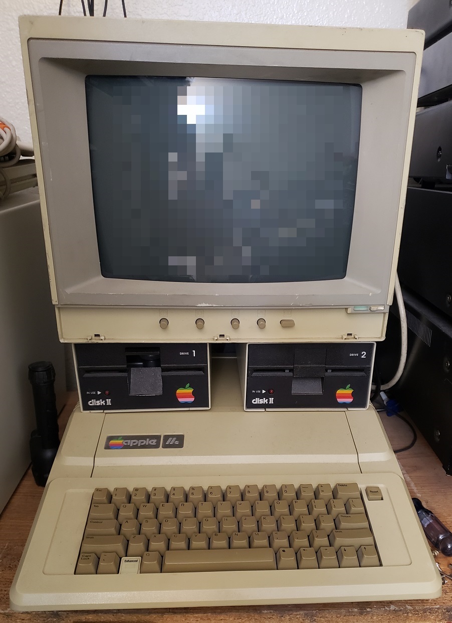
In my last article I wrote about the iconic IBM 5150. This time we are going to look at another machine of the eighties that is just as, if not more iconic, the Apple IIe. The Apple IIe or Apple II “Enhanced” is the third model of the Apple II line and was released early in 1983. It was the longest produced Apple II and with little doubt the most iconic of the line.
Like many computers of the early 80’s and unlike the IBM 5150, the Apple IIe used specialized chips and was only able to use its own software specifically for the Apple II line. The Apple II was a bit more expandable then some other micro computers such as the Commodore 64 and Tandy CoCo as it does have a number of expansion slots available which we will take a look at once we open the Apple II up.
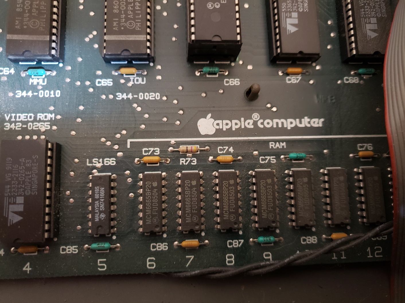
Keep in mind there were a few revisions of the Apple IIe. Mine appears to be the 1985 “Enhanced IIe” which involved several changes and upgraded chips which we will also talk about a bit later.
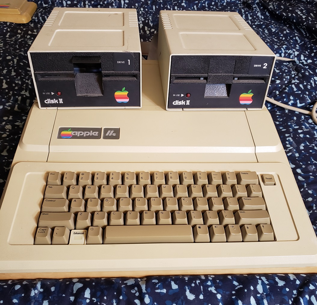
All versions of the Apple IIe were the popular at the time “keyboard computers” as in the computer was compact and featured a built in keyboard similar to a Commodore 64 or Tandy CoCo. The image above also features two DISK II 51/4 floppy drives which the Apple IIe was commonly found with. These drives accept 140kb Apple formatted disks.
I also have a cover for my Apple II’s keyboard. Its not in perfect shape but I’ve never seen another one.
Lets take a quick look at the monitor I’m using before taking a look at the rear of the apple II and then opening it up.
I am using the 13 inch Apple ColorMonitor IIe which is a composite color monitor that was widely used with the Apple IIe line. Mine is not in the best shape with a chipped power button and a missing front bezel but it works and the image is a good quality, generally higher then a similar consumer TV of the same size and time. There are several adjustment knobs as well as a “white button” which turns the Color IIe into a monochrome monitor.
The connector is a RCA style composite connector located on the rear of the monitor.
Unlike many of the home micro computers of the early 1980’s the Apple IIe line allowed for relatively easy expansion via expansion cards much like an IBM compatible PC. The Apple IIe does have a few built in ports located in the lower left hand corner.
Starting on the left we have a single RCA style composite jack for connecting to a composite color or monochrome monitor like the Apple ColorMonitor IIe or any standard TV with a composite input should work although Wikipedia states the output is “unreliable” and may have varied results when connected to anything besides a monitor.
video modes according to Wikipedia for the Enhanced IIe are as follows
40 and 80 columns text, white-on-black, with 24 lines
Low-Resolution: 40×48 (16 colors)
High-Resolution: 280×192 (6 colors)
Double-Low-Resolution: 80×48 (16 colors)
Double-High-Resolution: 560×192 (16 colors
Next to the composite out jack there are dual 1/8 input and output jacks for connecting a tape deck. Lastly is a db-9 joystick port. This port is for Apple compatible paddles and joysticks.
This port is physically compatible with Atari and Genesis joysticks and gamepads but is not electronically compatible and can cause damage if connected.
The joystick port was also used to support the official apple IIe mouse, the “Apple Mouse IIe” which is essentially a rebadge of the Apple Mouse II. I do not believe however that a large amount of software on the IIe supported a mouse interface.
Above these built in ports taking up expansion port cutouts 1 and 2 are the cables connecting to the dual Disk II floppy drives. Unlike most cards which would have a port on the rear of the card and be exposed on the rear of the computer through the expansion slot the apple II disk II controller card has dual internal pin connectors for the floppy ribbon cables. This means the cables connect to the card and then must be snaked out of the rear of the Apple IIe and to the drives.
Below is a Apple IIe disk II controller card
Down farther from the floppy drive cables at expansion port 6 is my Hayes modem card. I’ve never actually used this card but It came with my Apple IIe
The Apple IIe is relatively easy to open up and the cover can be removed by unclipping the two plastic tabs at the rear and then lifting up.
As I stated earlier my Apple IIe is the Enhanced IIe meaning that 4 chips have been replaced or “upgraded” including the CPU and three ROM chips in order to make the Apple IIe more compatible with the Apple IIc. These changes did fix a few bugs and increase compatibility with newer software but also introduced some slight incompatibility issues with a few older software titles.
1) CPU – The Enhanced IIe uses the 65C02 processor running at 1.023MHz on an 8-bit bus. This CPU is an enhanced version of the 6502 CPU found in earlier Apple IIe computers and offers bug fixes, lower power draw and some performance improvements.
My Apple has the 65SC02 CPU which is a variant lacking bit instructions. Below is the official Apple IIe enhancement kit that included the updated 65C02 CPU and accompanying ROMS.
2) RAM – The Enhanced IIe like the Apple IIe before it comes with 64kb RAM built into the motherboard. This was fairly easy to increase up to 1MB by use of RAM expansion cards.
One common card used for expanding RAM on the Apple IIe was the 80col/64k card. This card when installed in the auxiliary slot on the motherboard added 64k of additional RAM bringing the total system memory up to 128k and allowing 80 column mode to be used.
My Enhanced IIe came with a RAM Works card from Applied Engineering. This card when installed in the auxiliary slot operated exactly like the 80col/64k card except it could upgrade your system memory all the way up to a full 1MB of RAM.
As far as games go I’m not sure any games required or took advantage of more then 128k of memory although several utility/productivity programs either required or ran better with more RAM on the Apple IIe.
3) Expansion slots – The Apple IIe used seven 50-pin Apple IIe Bus slots for expansion. This worked very much the same way as it does on any IBM compatible as you can buy various compatible expansion cards and simply install them in the slots. These cards ranged from the disk drive controller to modems, sound cards and even hard drive controller cards.
4) Auxiliary slot – The Auxiliary card slot is a 60-pin slot designed specifically for certain Apple IIe compatible cards. Primarily these were memory expansion cards but RGB video adaptor cards also used this slot.
5) Various connectors can be found on the right side of the IIe motherboard. The connector labeled “keyboard” is obviously for the built in keyboard cable. The “numeric key pad” connector is for adding an external numeric keypad which you would need to snake the connector cable out one of the various openings on the rear of the computer. Finally the game I/O is simply another internal game joystick/paddle port.
Sound – Sound for the Apple IIe was provided by a simple cone speaker. There were sound cards produced for the Apple IIe line such as the Mockingbird card but very few games seemed to take advantage of these cards.
Upgrades
Besides expanding the memory for my Enhanced IIe to 1MB there was also a few other simple upgrades I was able to try out.
The first was upgrading the dual Disk II drives to something that looked a little better. The dual drives worked fine but I feel like they looked a little crude and having both drives essentially hard wired to the case unless I removed the lid and disconnected them internally from the card made moving the Apple IIe a bit of a chore.
Thankfully in 1983 Apple released the DuoDisk which took two disk II drives and placed them inside a single case which connected to a controller card via a single detachable cable.
The second upgrade I tried was an accelerator card. The card I tried was the Titan Accelerator IIe. The Titan accelerator features the same 65c02 microprocessor as the IIe but this one runs at a blazing 3.58MHz and adds 64k of memory.
My card has a R65C02P4 processor installed which is supposedly running at 4MHz. Unfortunately, I didn’t have much working Apple IIe software to do testing at the time but the game Planetfall which I did test did not seem to be running any faster than before and would lock up when landing on the planet while the Titan accelerator was installed.
Since all Apple IIe computers used the same CPU at the same speed rating games by nature were fined tune to operate at 1.023MHz and thus I find using any accelerator in an original IIe to be dubious at best. The added speed may be of benefit with some productivity software but since most of us retro computer enthusiasts primarily enjoy gaming on original hardware I feel like an accelerator may do more harm than good in an Apple IIe by throwing off the timing of games or even flat out locking up or refusing to run the software.
The Apple IIe is an iconic computer that any hardware collector needs to have in their collection. The enhanced IIe is a pretty good choice when looking for an Apple II and should play most games and software just fine though keep in mind some older games may not function correctly due to the updated ROMs and CPU.
Unfortunately in the time I had my Enhanced IIe setup I found it getting fairly little use. Although there is a huge number of games available on the Apple II I found myself primarily running their ports on other machines which offered either superior visuals and sound or better ease of use. Despite the huge amount of games for the Apple II there seem to be relatively few exclusive titles and the titles that are exclusive seem to go for large sums of money on sites like eBay.
There were personnel computers before the IBM 5150 but the 5150 is the computer that solidified what an IBM compatible PC would be. The 5150 featured an x86 processor, internal slots for various upgrade cards and was primarily intended to run off of PC-DOS / Microsoft MS-DOS operating system, all things we would learn to associate with the future IBM PC compatible market. The IBM 5150 was released in 1981 and was primarily intended as a machine for serious business tasks but was certainly capable of playing games and performing other non business functions.
The overall construction of the 5150 is extremely sturdy with a heavy metal case. The face of the case features no buttons or LEDs that we expect from later PCs and just features a stylish IBM PC badge, some vents and dual full height drive bays. The 5150 was sold in a few configurations including dual and single floppy drive variations as well as a version with no drives at all.
The dual full height bays commonly housed one or two 160k/360k (single/double sided) floppy disk drives. You can add two half height drives into these bays though this will require some means to secure the mounting as the bays are designed only to secure full height drives.
The power button is located on the left rear side of the 5150 case and uses a large on/off switch.
A locking mechanism was sold by IBM which one would place over the power switch which allowed the PC to only be turned on with the use of a key though I believe this also worked with XT and AT models as well.
Lets take a quick look at the rear of the case.
On the left side we have one female and one male power port. the male connector uses a standard three prong power cable with the female connector intended for a monitor to to plug into. To the right of the plugs we have a large round vent for the power supply followed by a keyboard and cassette connector. On my PC these ports are conveniently labeled.
The original keyboard for the IBM 5150 is the model F.
Model F keyboard
The model F is similar to the later model M in that it is very well built and does feature “clicky” keys. As you can see above the function keys are located to the left and there is no space between the num pad and the rest of the keys. This is a PC/XT class keyboard and will not work on later AT class machines.
The cassette port located next to the keyboard port was rarely used on the 5150 though I suppose if one had purchased a variation without any disk drives this would have been the expected method of data transfer. Finally we have five slots for adding expansion various cards.
Before opening this case up and looking inside lets take a quick look at the monitor.
The intended monitor for the 5150 was the IBM 5151 green monochrome monitor. Being mostly intended as a machine for office use where sharp text took priority over color, although IBM did release a color CGA and EGA monitor with very similar styling. The 5151 monitor gives a very nice and sharp monochrome image and is also surprisingly light compared to the general heft of the 5150. The two dials are for controlling brightness and contrast.
Unfortunately the two power cords on the 5151 are hard wired to the monitor itself. One cord is a 9-pin connector to connect to a monochrome video card with the other being the power connector intended for connecting to the female plug on the 5150’s power supply. There is no power button on the 5151 as the monitor was intended to power on with the 5150.
OK, now lets take a look at the inside of our 5150.
Take note that I have upgraded the power supply in these images to a 130w power supply in order to accommodate a possible hard drive. The stock power supply in the 5150 is a fairly anemic 63w supply and may not supply enough power if a hard drive is added.
There were two motherboard versions released for the 5150 depending on when it was manufactured. Earlier models used the 16kb-64kb boards which only were capable of supplying a maximum of 64kb of RAM on the board’s RAM sockets. My 5150 uses the later 64kb-256kb motherboard indicating a total of 256kb of RAM could be installed on board.
1 ) CPU – The CPU is the classic 8088 running at 4.77MHz. This was a cost saving measure as the 16-bit 8086 would have been faster but more expensive. Keep in mind that the NEC V20 which offered a slight speed boost over the 8088 was a fairly common upgrade on these machines.
1.5 ) math copro – Located alongside the CPU socket is the FPU socket for adding an 8087 math co-processor if desired.
2 ) RAM – My PC has been upgraded to the full 256kb of memory. Notice how the first row of memory is directly soldered to the motherboard while the following three rows are socketed.
3 ) PC Speaker – The 5150 uses a real PC speaker located on the far side of the case.
4) Switches – Two switch blocks located on the motherboard are used for setting things such as installed memory, type of video card installed ect… switch settings as well as a large amount of other information on the 5150 and other IBM PCs can be found here.
Lets take a look at the various expansion cards I have installed in my 5150.
Unlike later IBM PC compatibles which upped the standard expansion slot count to eight the 5150 only sports five 8-bit ISA slots. This can be a little limiting considering there is virtually nothing built in as far as video and I/O goes as well as the fact that your going to most likely be losing one ISA slot right from the start to a floppy drive controller card.
This is the standard IBM floppy controller. It features an external floppy port and when paired with the 5150 can support up to four floppy drives. Drives connect via the edge connector on the rear of the card. This card is currently running my dual 160k/360k drives but is also capable of supporting 720k 3 1/2 inch floppy drives.
Next up of my currently installed cards we have the monochrome video / printer card.
The IBM monochrome monitor card (MDA card) is designed to connect to the 5151 monochrome monitor and you will usually find this card installed in almost all 5150’s. The MDA card is not capable of displaying pixel graphics but only characters thus making it largely unsuitable for games but great for business which mainly benefited from having a sharp text display. There are games like Rogue which can be played on an MDA monitor since it only uses text and characters for graphics. Thankfully IBM understood the situation with limited expansion ports so the IBM MDA card also included a printer port.
An option even better then the IBM monochrome card would be a Hercules card or Hercules compatible card. These cards also worked with a monochrome monitor and featured a parallel port but also had the added benefit of being able to display graphics on a monochrome monitor for games which supported Hercules mode and with a small program even emulate CGA graphics in monochrome.
Thankfully you could also install a CGA card (as well as an EGA or VGA card) in the 5150.
There are a few revisions of this card from IBM with minor differences but I am using a later revision here. Although you can install a EGA and even some VGA cards in the 5150 I find the machine lacks enough power and RAM to properly run those sorts of games and is best suited for playing CGA titles. There are also a number of later more advanced CGA cards from companies like ATI which offer more display modes in a smaller form factor but I was trying to keep things more or less IBM and early 80s with this build.
Most commonly CGA offers games to be played with four colors from just a few palettes. Black, Cyan, magenta, white is the palette most associated with CGA though there are other palette options.
The IBM CGA card also offers a composite out for connecting to a standard TV. This produces a less sharp image then CGA on a computer monitor but techniques like dithering can be used to blend colors and create an image resembling EGA in some cases.
You also have the option, like I have done with my 5150, of installing dual video cards. I currently have both a MDA and CGA card installed. You can switch back and forth between MDA and CGA monitors with a DOS command MODE CO40 for CGA 40 column mode, MODE CO80 for CGA 80 column mode and MODE MONO for the monochrome display in 80 column mode.
The final card I have installed is an AST MegaPlus II card.
multi function cards like the MegaPlus II and the AST SixPack Plus were fairly common for the IBM 5150. The lack of expansion slots gave an opportunity for third parties to step in and create expansion cards which incorporated several useful features into one card. The MegaPlus II adds a real time clock, up to 512kb of memory to bring your 5150 up to 640kb, a serial port as well as multiple headers for daughterboard expansions.
Adding a hard drive / 720kb floppy drive
I kept my 5150 fairly stock and period correct but for some extra quality of life adding a hard drive and 720kb floppy drive is fairly simple.
The first issue you’re going to have with adding two half height drives is that the bays were only designed to securely mount a single full height drive as we can see in the image below.
Any upper drive would have no points to mount to. Thankfully there are some solutions as mounting plates were made to allow the use of dual half height drives. Theoretically I suppose if you had some sheet metal and tools you could create your own mounting plates. Below is a mounting plate I used, unfortunately it has no labeling so I’m not sure if it was homemade or part of some official kit.
If you do not have a mounting plate I found improvising works just as well though may it may not look as eloquent of a solution. I was able to position a mounting rail from a random PC diagonally and use it as a fairly sturdy mounting solution.
Once the mounting situation has been taken care of its time to well….mount the drives. Mounting the 3 1/2 720kb is fairly simple as even the stock IBM floppy controller will support it. You just either need a cable with the correct connectors or install a pin to edge connector adapter on your 720kb drive and it should run just fine. Newer 1.44mb drives will also work as 720kb drives without issue.
Installing a hard drive is a little trickier as the stock power supply is under powered for the task and the 5150 was not initially designed with a hard drive in mind as IBM never offered a hard drive as an option although later it did offer a 5161 expansion unit which did house a hard drive but which was the size of the entire 5150. Your first task is to upgrade the power supply with a beefier one. I upgraded mine to a 130w supply.
If you want to be more period correct you will want a MFM or RLL hard drive controller. I used a WD controller as well as an ST-225 20MB drive which worked without issue for me.
If your not trying to be period correct your best bet would probably be an XT-IDE controller with a CF card as these draw much less power then period drives and offer much faster speeds and reliability.
A friend once asked me why I would want a 5150 and proceeded to ask me if I “wanted to emulate being a 1980s office worker”. This comment is actually pretty fair since the 5150 is first and foremost a business machine. You certainly can play games on it and with a little work upgrade it well for this purpose but in truth there are many better options if you’re looking for an early 80’s 4.77MHz niche machine. The weak power supply and limit of five expansion slots does not do the 5150 any favors. If you want an early 80’s 8088 based machine find or build a nice machine with eight slots a turbo button and 640kb of memory built in.
On the other hand as a collector of vintage PC hardware the 5150 is a no brainer, it needs to be in your collection. The 5150 is iconic and set the stage for all IBM PC compatibles for decades to come.
Around four years ago I wrote an article on this blog about the very similar IBM 300PL Type 6562. I picked up this machine because I really liked the style of the case but it really wasn’t the model I was looking for. Finally, several years later I finally acquired my IBM 300PL 6862.
The case is more or less identical in style and size to the 6562 except it lacks the audio input/outputs and volume control under the floppy drive. On the left side of the case we have a large power button with three LED indicator lights underneath for power, HDD activity and network activity. Near the center of the case is a slot meant for a 1.44MB floppy drive. To the right side of the case we have 2 5 1/4 drive bays with one being occupied with a CD-ROM drive, though in this case it is not the original drive.
Turning the case around we can tell right away by the orientation of the four expansion slots that this machine uses a riser card. Starting under the expansion slots mid-case and moving right we have our various built in I/0 ports. First we have three audio jacks for the built in audio for a microphone, line in and finally line out. Next we have an Ethernet jack followed by a parallel port, dual USB 1.1 connectors, dual serial ports, two PS2 ports for mouse and keyboard and lastly a VGA connector for the built in video. Above the VGA port is another unusual cutaway. This is for the possible addition of an AGP card which we will take a look at once we are inside the case.
The case lid is pretty easy to remove and just requires lifting two tabs at the back of the case and pushing it forward and up. The IDE hard drive is mounted out of sight below the CD-ROM drive and below the second 5 1/4 bay.
Here is the handy data sticker found on the underside of the case cover though note that I found it wasn’t 100% accurate which we will talk about. This may be due to me updating the BIOS to the latest version.
And next lets take a better look at the motherboard.
The motherboard is an NLX form factor board which some manufactures like IBM and Intel pushed in the late 90’s. It was meant to be a low profile, low cost motherboard form factor and had some odd quirks like the AGP port placement on this board which is located far from the other PCI and ISA slots and, for the most part, requires NLX form factor video cards. It’s a little hard to see in the images above but the motherboard connects to another brown colored edge connector located where the riser slot is located.
1 ) CPU – The Type 6862 motherboard uses a slot 1 socket and supports both Pentium II and III slot 1 CPU’s. My particular machine came with a 450MHz Pentium III, the lowest clocked Pentium III, and also had what I’m pretty sure a cooling fan added on by the previous owner.
The sticker on the underside of the case lid gives switch positions for installing a Pentium III up to 550MHz but with an update to the latest BIOS I was able to successfully upgrade the CPU to an 800MHz Pentium III and using a Power Leap adapter was even able to install a 1.3GHz Tualatin. A few things to note however is I found the switch settings useless when upgrading the CPU and when I changed them from what was the systems default I even ran into POST errors. I suspect this may be an issue caused by the BIOS update which changes how CPU speed is handled. I did however run into a separate POST error after changing CPU’s that I had to go into the BIOS advanced features menu and disable “CPU BIOS update”.
Also note that there are no power connectors on the main motherboard for the CPU fan but there is one on the riser board which can be used.
2 ) RAM – The Type 6862 officially takes up to 384MB of PC100 SDRAM. My machine was able to recognize 512MB with the BIOS update under Windows 98se. I am currently using two 256MB sticks of PC133 which work at PC100 speeds on this motherboard.
3 ) Video – The built in video chip is a S3 Trio 3D with 2MB of SGRAM. The Trio 3D is more or less the successor to the Virge line of 3D acceleration chips and like them it has great 2D compatibility with older DOS titles but 3D is somewhat lacking. For retro gaming I strongly suggest upgrading with an AGP card unless your strictly going to be playing 2D titles.
4 ) Sound – Sound is provided by a Crystal CS4235-KQ chip. I don’t have much experience with this chip but the datasheet indicates it is Sound Blaster, Soundblaster Pro and Windows sound system compatible though being a budget chip I wouldn’t be surprised if the FM synth was not up to par with a true Yamaha OPL chip. For general use in Windows it should suffice but if you want to use the 6862 for gaming I would advise disabling the built in sound and adding an ISA or PCI sound card depending on your needs.
5 ) As was mentioned earlier the Type 6862 uses a riser board like many Desktops. on this riser board we have various connectors such as the power connector for the CPU fan as well as three PCI and two 16-bit ISA slots. This should be more than enough for adding sound and video cards depending on your needs.
If you look below the riser you can also see the long brown slot the motherboard itself connects to.
When installing expansion cards each card does not get its own screw to hold it in place but the case used a metal bracket that unscrews and then screws back on to secure any added cards.
6 ) AGP slot – Unusually on this board the AGP slot is located far away from the riser card and the other PCI/ISA slots. On a technical level it does not make much if any difference though it can cause issues if you were hoping to run a certain setup such as using a Voodoo 1 or 2 or any card that requires some sort of cable connection to your primary video card.
The other issue this arrangement causes is that due to the special video backplate used you need an NLX compatible video card with its video connector high on the card. Usually, these cards also have a little square cut on on them on the lower half under the video connector.
NLX compatible card on the right along with bracket adapter. None compatible card on left.
Thankfully Diamond Multimedia made a large number of NLX compatible video cards and most late 90’s video chips can be found in this form factor such as the Voodoo3, TNT 1 and 2, Matrox G200, ATI Rage 128 and others. The most powerful card sold in the NLX form factor was the Geforce 256 SDR though they tend to sell for quite a large amount of cash these days.
ATI Rage 128 in NLX form factor and proper bracket adapter attached.
I quite like the IBM 300PL Type 6862 and it’s quite versatile. You can easily install a low clocked Pentium II along with an ISA sound card and have a fast DOS rig. On the other hand, it also makes a great Windows 9x retro PC depending on your era of choice determined by your CPU and video/sound card choice. The ability to support everything from a Pentium II 233MHz all the way up to a 1.3GHz Tualatin via a power leap adapter makes this a very versatile retro PC.
The case is a bit large however and does take up quite a lot of desktop space. Other annoyances such as the odd arrangement of the AGP slot slightly limit your video card options but despite this the 6862 makes a great late 90’s retro PC.
Today we will be taking a look at a pretty solid 286 PC from the late 1980s. The VTI Turbo 55 although not noticeable at first is actually a Samsung branded PC which becomes obvious if we take a look at the sticker on the back or at the motherboard itself. First though let’s take a look at the front of the case.
On the front we have a keyhole for locking the computer along with two LEDs for power and HDD activity. Below this is what looks like a third LED at first but its actually a slightly recessed reset button. It’s a double-edged sword though as the recessed button does make it almost impossible to accidentally reset the PC it also makes it a potential pain if you do want to use the button to reset as you’ll need a pen or otherwise small object to use to press the button. There is no power button on the Turbo 55 so turning the power on and off is performed via a switch on the power supply.
To the right of these LEDs and reset we have two 5 1/4 drive bays. Mine are occupied with a 1.2MB 5 1/2 floppy drive as well as a 1.44MB 3 1/2 floppy drive. As I have the original box with the original specs printed on it seems this PC came stock with only the 1.2MB 5 1/4 drive. The 1.44MB drive was a later addition from the previous owner. Two bays do not leave much room for expansion but for a 286 class PC you’re perfectly fine with a pair of floppy drives. If you really wanted to you could always track down a dual floppy drive and use the second bay for a CD-ROM drive or something along those lines.
The Turbo 55 is one of those PC’s that have the keyboard connector in the front which I’m not the biggest fan of though this is a largely personal preference
The keyboard itself is pretty well made and feels like a model M with nice clicky keys. There is also an XT-AT switch on the underside in case you wanted to use it with an even older PC in your collection.
flipping the case around let’s take a look at the back.
You may notice the power supply looks well…incorrect. You would be right to think that and we will address that in a moment but first we will take a look at the built-in I/O ports. From left to right we have dual serial ports followed by a parallel port. Not a lot but as far as 286 PCs go it’s really nice to have anything built-in. Next to the parallel port we also have a curious switch with M below and C marked above. According to the documentation I could find on this model this is a monitor select switch with the M standing for mono and the C for color. The switch made no change as far as I could tell but I was using a later VGA card when I tested it so maybe it only works with CGA cards. To the right of this we have eight expansion slots with one being currently occupied by the EGA card.
Before opening the case and taking a look at the inside we can quickly talk about the power supply. The original power supply was a Han One HN-200c which when I received this computer was unfortunately completely dead.
In my foolishness though I ended up throwing it away since I just assumed it was a run of the mill AT power supply. In actuality the dimensions are a bit non-standard. The power supply I have installed currently is a newer ATX supply with an AT adaptor. It doesn’t fit quite fill the entire space so I just used some foam to fill the gap. Due to the lack of a power button I had to make sure the replacement PSU had a physical on/off switch.
The power connector on the motherboard itself is AT and any AT power supply (or adaptor) will connect to it just fine though the original HN-200C power supply did not have a split AT connector like most standard ones do.
With that out of the way lets take a look inside this PC.
Before we take a look at the motherboard lets take a look at the two expansion cards that were installed when I originally acquired this PC. If you look at the image above you’ll notice the hard drive is mounted in a vertical orientation to the right of the floppy drives.
The hard drive is run off the 8-bit controller card above and is the uncommon XT-IDE or XTA interface. This is a seldom used interface only supported by a hand full of hard drives. The Commodore Colt I reviewed some time ago also used this interface for its hard drive. The hard drive attached is a Microscribe XTA hard drive of 40MB size. I do believe this controller card and hard drive are original to this PC. Unfortunately after several hours I could not get the VTI Turbo 55 to work with any 16-bit IDE controller or SCSI hard drive controller despite the PC having 16-bit ISA slots. Fortunately for me though the stock XTA controller and the hard drive still are functional.
The only other expansion card installed was the video card.
The video card was an ATI EGA Wonder 800. I couldn’t find much information on this card but ATI was known to make some of the better cards of the time. The EGA 800 is also known to support extended EGA text and graphics modes as well as 16 color VGA modes. For convenience and due to my lack of a proper EGA monitor I replaced the card in my Turbo 55 with a slightly later 16-bit ATI VGA card.
1 ) CPU – The CPU is an AMD branded 286-12 running at 12MHz. Interestingly this 286 is the N80L286-12 which is the lower powered variant running at 2.89W as opposed to 3.15 or 3.3W. the 286-12 was along with the 286-16 the quintessential and most common 286 CPU’s. Although fast enough to trigger issues with the more sensitive games meant for a slower 8088 when paired with decent VGA video card the 286-12 should have enough muscle to adequately run some slower paced VGA titles, specify point and click adventure titles.
2 ) FPU – As in most cases, my Turbo 55 came with an empty FPU socket and is a completely optional addition. For my Turbo 55 I chose to add a 287XL FPU. Unlike adding a standard 287-12 which would run at half the speed of the installed 286 (6MHz) the 287XL is actually a modified 387 FPU and should run at the full speed of the CPU which in this case is 12MHz. As I always feel obligated to mention the 287 regardless of its running speed will probably find very little use in this PC as very few games of the era took any advantage of a math co-processor chip. I did however find a CAD program installed on the hard drive which would be an application of the era that would have benefited from this upgrade.
3 ) RAM – My Turbo 55 came with a full 1MB of memory on the motherboard though from what I can see on the box 640KB and 512KB options were available. 1MB would be more then enough for a 286 class PC such as the Turbo 55 and more RAM could always be added via ISA memory cards such as the Intel Above Board if so desired.
Half of the RAM chips on the motherboard are directly soldered on while the other half are socketed.
4) Floppy connector – The floppy controller is built-in and supports up to 1.2MB and 1.44 high density floppy drives.
5) Power connector – standard AT power connector.
The serial and parallel ports can be disabled via the jumpers 11 through 14 located above the RAM while wait states can be set from 1 to 0 via jumper 21 located under the 5 1/4 bays. When I set my wait states to 0 I noticed a significant speed increase but unfortunately this created many stability issues making the machine virtually unusable.
The VTI Turbo 55 is a capable 286. It can be argued that the 286 is a fairly useless CPU for modern retro PC enthusiasts as they are to fast for earlier games while for later titles a 386 can run everything a 286 can but vastly better. I personally still find a certain charm in running a 286 system and the Turbo 55 does in my opinion make a fine 286. The 12MHz speed gives you some wiggle room for playing games and with the right video card even lets you play some slower paced VGA titles just fine. 1MB of RAM is just about perfect for the time and considering the CPU you’ll likely not feel the need to play any games requiring more than the on board 1MB of memory. If you do there is always the option to add more memory via an expansion card.
Most of my negatives of the Turbo 55 are fairly minor such as the frontal keyboard connector or the unnecessarily, at least in my opinion, recessed reset button. The biggest issue I had with the Turbo 55 was the difficulty in adding a different type of hard drive controller. XTA is a very limiting hard drive interface considering it only works with a handful of now 25+ year old hard drives of limited capacity. I tried multiple 16-bit ISA IDE controllers and drives as well as multiple SCSI controllers and drives and found none to work. This does seem to be an issue common to some 286 class motherboards and unfortunately this seems to be one of them. I did not test a modern XT-IDE controller but hopefully maybe one of these would work as a hard drive replacement.