Way back in Jan of 2016 I wrote an article on the slot loading iMac G3. This time we’re going to take a look at the original Bondi blue “tray loading” iMac G3 and see how this iconic computer that is often times referred to as “the Mac that saved Apple” compares to its later “slot loading” revision. In this article we will be looking at a more or less bone stock very first revision or revision A model originally released in August of 1998.
As I stated in my original post on the slot loading variant of the iMac I was not the greatest fan of the Mac and was firmly in the Wintel PC camp during that time. My disdain for the iMac though was at the height of my displeasure with all things Apple and I honestly did not know why anyone would want one of those computers. Time and experience though has softened my stance and I now can appreciate these computers for what they are and the use they were intended for. The all in one iMac G3 was not a new idea but it was an idea that Apple as a company had moved away from during the latter half of the ’90s to make more generic “PC” type machines and hence lost a lot of what made Apple unique and stand out in the market. The iMac G3 was an all-in-one machine and was extremely simple to set up and played with Apple’s strength of focusing on industrial design with a colorful and inviting Bondi blue colored shell as opposed to the standardized beige of almost all other PC cases. The iMac was intended to be extremely user-friendly and be simple to set up like a microwave or a toaster. This computer was aimed at the average user just wanting to “surf the net” or write school assignments rather than power users or gamers (even though the iMac certainly could be gamed on).
The original model seen here only came in Bondi blue as opposed to later models that were offered in a variety of colored shells. A handle was provided at the top to help move the Mac around but to be honest it always feels a little awkward to use and I always feel like it’s going to snap off despite the handle being very sturdy.
The bulk of the iMac is taken up by the built-in 15-inch shadow mask CRT monitor capable of resolutions up to 1024 x 768. The iMac G3’s kept this same spec monitor throughout all models though later slot loading iMac’s supplied an external VGA port to connect to an external monitor. These early tray loaders did not which makes it quite unfortunate if your monitor dies. The rear of the Mac hides only a small handle, which is used when removing the motherboard, and a standard 3-prong power connector.
They also came with a matching Bondi blue iMac keyboard and mouse. The keyboard is a simple Apple USB keyboard and is not so dissimilar from others besides the color but the mouse, a USB ball type mouse, is the infamous “puck mouse” so called because of its hockey puck like shape.
Unfortunately the rumors of the poor ergonomics of the of the puck mouse are completely true and the mouse can be very awkward and uncomfortable to use over any extended period of time. This isn’t a major problem since the mouse can be swapped out with any Apple USB mouse including later Apple Pro mice which use a standard shape and sports a laser as opposed to the older ball for tracking. The puck mouse also uses the traditional one-button Apple style mouse so no scroll wheel. The mouse has held up well though I’m not sure if this is from rugged construction or lack of use.
The iMac was famously the first Mac to drop the floppy drive although one was easily added via a USB port. In its place a 24x CD-ROM drive was standard and is located below the monitor. The early runs of the iMac used a tray loading CD drive, hence the “tray loader” title where as the later models used a self-loading slot mechanism. Next to the CD drive we have a power button that emits a soft green light when on and on the right and left sides we have two built-in stereo speakers. These speakers do have a habit of rotting a bit but it is a repairable issue and fortunately this particular iMac does not suffer from the foam around the speakers deteriorating.
The speaker on the left has a wireless 4Mbits/s IrDA inferred sensor which was removed starting with the revision C tray loaders. The right speaker has dual 1/8 stereo jacks for hooking up headphones that two users can use at once which is quite nice. Underneath the Mac is a fold-out stand of the same Bondi blue as the case.
On the left side of the iMac we have a small compartment housing some various ports. The is a plastic cover which can either be removed entirely or replaced after your various peripherals are plugged in and the wires snaked out through the several openings provided.
Once the plastic cover is removed we are greeted by a variety of ports.
On the left we have two more audio jacks, one for a microphone and a second for optional external speakers, handy if the built-in speakers fail or are not powerful enough for your liking. Next to that is a scant two USB 1.1 ports. The iMac is also known for going all in on USB and ditching the traditional Apple ADB ports in favor of USB though I wish more USB ports were made available. The mouse is generally expected to plug into the USB port on the keyboard (this why the cord is generally so short) and this does help free things up. A USB hub can also be used without issue in case you have multiple USB devices you want to use. Next we have a 10/100 Ethernet jack and lastly a 56k Modem jack.
Under these ports we have a mysterious little covered cutout held in by two screws. Behind this cover is what is commonly called a “mezzanine slot”. This is a sort of expansion slot that originally was only supposed to be for Apple’s internal use but you can use it for other things and third parties did make expansion devices that took advantage of the presence of this slot though from my research they seem to be extremely rare. I even know of at least one third party adaptor that uses the slot to add a 3DFX Voodoo II upgrade and according to Wikipedia SCSI and TV tuner cards were also available though I’ve never seen any of these cards in person. This port was removed along with the previously mentioned inferred sensor with the tray loading revision C model.
Opening the iMac is much easier then it is on later revisions and there is no “mesh” layer present that requires removal. You just need to remove a few screws on the underside and then use the handle to pull off the plastic case section. Once the outer case is removed as well as a few more screws and cables the motherboard assembly will slide out though be careful as with most older Macintosh computers the plastic casing can be delicate and things tend to snap off.
Here is the underside of the case with the motherboard assembly removed. The early tray loaders sport a fan for cooling as seen here while the later slot loaders used a fanless convection process to cool internals.
Here we have the tray that holds the motherboard and most of the iMac’s components completely removed from the case. The hard drive is located under the CD-ROM drive as seen in the image below. Mine came with the original 4GB 5400 RPM drive.
Originally the iMac came preloaded with Mac OS 8.1 or 8.5 with the ability to officially upgrade to OS X 10.3.9 though mine has been upgraded to OS 9.2.2.
1 ) CPU/RAM – The CPU and RAM on the tray loaders were both located on daughterboards that connected directly to the main motherboard. The metal cage enclosing the daughterboard easily wiggles off with some light force. Revision A as seen in this article and revision B iMacs only shipped with a 233MHz PowerPC 750 G3 processor w/ 512kb of L2 cache but later revision C and D tray loader iMacs had 266MHz and 333MHz CPUs installed.
CPU module top
CPU module bottom
Standard RAM amount was 32MB of PC100 SDRAM in a smaller laptop style form factor. The revision A iMac was expandable officially to 128MB and unofficially to 384MB. Revision B, C and D were officially expandable to 256MB and unofficially to 512MB. My machine came with the oddly numbered 288MB of RAM installed. It seems the previous owner did make the sole upgrade of adding a 256MB stick of memory in addition to the 32MB of RAM already installed.
I had no problem up upgrading my RAM to a full 512MB by installing two 256MB RAM modules despite being a Rev. A motherboard and sources online indicating 384MB being the limit.
2) Video – Original revision A iMacs shipped with a built-in Rage IIc chip and 2MB of SGRAM as seen on my iMac but this was quickly changed in revision B and up tray loaders to the much more powerful Rage Pro chipset with 6MB of SGRAM standard. The original revision A boards can be upgraded to a full 6MB of SGRAM.
The ATI chip isn’t a surprise as Apple has a history of using ATI chips for graphics in this era. As far as I can tell the revision A iMac G3 is the sole computer to use this specific version of the Rage chip built in. Overall the Rage IIc is an adequate chip, though by 1998 it was getting quite outdated and was seen as a entry level 3D video chip. 2D applications should run just fine as well as less intensive 3D titles as long as resolutions and features are kept in check.
with 4MB extra video RAM module
3) Sound – Sound has always seemed like a bit of an afterthought in Apple machines and finding specifics has always been a bit of a chore as sound chips aren’t commonly noted on spec sheets. The iMac would appear to use Crystal CS4211-KM chip which supports simulated surround sound via the two built-in speakers.
4) Battery – Lastly we have the PRAM battery which acts just like the CMOS battery in a standard motherboard. Be sure to replace this on any newly acquired Macintosh computer.
Accessories
Compucable iDock II
The iDock is an interesting accessory that was designed for the iMac to extend its capabilities. My version is the iDock II which features a built-in 1.44MB floppy drive. As far as I can tell the floppy drive is the only difference between the iDock I and II. The iDock connects to the iMac by way of a standard USB cable and requires its own power supply.
The top of the iDock swivels allowing you some measure of turning your iMac which sits on top of the iDock.
The rear of the iDock features several ports to expand your iMac such as four USB ports, two Geo ports and one ADB port. The ADB port has been reported to not work or only partially work on these units. On mine I was able to get an ADB mouse to work but it was very iffy and the response was poor. The iDock does require special drivers to function.
The iMac does what it set out to achieve and I can see now what I couldn’t see as my high school self, why the iMac succeeded. It wasn’t meant for people like me. It was meant less for hardcore PC gamers and those that liked to expand and tinker with their computers and more for the everyday user, the soccer mom, the person that just wanted to do homework and surf the internet and it made a pretty easy to setup and usable computer to sit in the corner of the family room and have for general family usage.
As a collectors piece the Bondi blue iMac is certainly worth adding to the collection and holds a significant place in computer history and especially Apple’s history. They are still relatively inexpensive as of 2019 though an original revision A may take some work track down and identify. If your purely looking for a Macintosh for late 90’s gaming though there are much better options. Personally, I think your better off acquiring a Power Macintosh G3 tower or desktop simply for the vastly greater options you get in upgrading (such as PCI slots) and higher ease of repair. Failing finding one of these a later slot loading iMac or even a G4 could make a good choice as they seem to be easier to source and are more powerful out of the box.
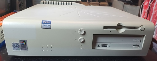
If Cadillac made PC cases I feel like the Dell XPS 420 case would be in their lineup. The case is elegant, functional and looks like a million bucks. I honestly love this case. The high-end Dell XPS line which stands for Xtreme Performance System dates back to the 1990s and were sold alongside the Dell Dimension series. The PC we will be looking at in this article is the model 420 from the XPS 400 line and dates from around 2005-2006. The 420 was intended to be a media-based home PC but please keep in mind the XPS 420 we will be looking at here has been significantly upgraded in some areas from its factory stock configuration.
One of the first things you may notice is the shiny piano black face plate giving the 420 an elegant look. Originally these PC’s shipped with Windows Vista but I have upgraded the OS to Windows 7 and replaced the OS badge.
Starting from the top and going down we have two 5 1/4 bays with covers that fold down of which one currently houses a DVD drive. Below these we have two 3 1/2 inch “flexbays” which allow for the addition of a hard drive, floppy drive or various audio/video input/output interfaces. Also on the front we have a mic and 1/8 audio jack as well as two USB 2.0 ports and one IEEE 1394 port. Lastly, we have a power button below these ports followed by the model and Dell badge.
The back of the XPS 420 at first looks very stark to the eyes of a retro gamer but that is mostly because the 420 lacks almost any legacy I/O ports. No serial, parallel or even PS/2 ports grace the back panel but you do have everything you need for a more modern machine. I’ll admit, I would have liked the 420 to at least have a parallel port to make it more useful if used as a more retro XP machine but the less cluttered I/O shield does have a sort of minimalistic charm.
At the top we have audio jacks including an optical audio out. Below this is an Ethernet jack and six USB 2.0 ports. It is recommended you connect more permanent devices such as keyboard and mouse via these rear USB ports. Further down in a second smaller cluster we have a coaxial digital audio out as well as an IEEE 1394 port and an eSATA port.
One of the more unique features of the XPS 420 case is the mini LCD screen on the top front as well as the diagnostic lights to the left. The diagnostics lights essentially serve the same purpose as post “beeps” from an internal speaker or piezo speaker only instead of using a combination of timed beeps it displays a number code using 1 through 4. The diagnostic lights have been used on earlier PC’s and I find this method a little more subtle and quicker to understand than the beeping method but it’s nothing groundbreaking. Next to the diagnostic lights we have two more lights, the top light being a network activity indicator and the lower light being a hard drive activity light. All lights on this top display use a very pleasing blue
Occupying the majority of the panel is the LCD and controls powered by Windows Slideshow. To the right of the LCD screen we have a menu button and below that a navigational and selection buttons.
The LCD itself acts as a sort of mini built-in monitor and according to the manual it allows you to perform tasks such as browse web pictures, view photos stored on your system, play or browse audio and video files, set reminders and alarms, monitor PC settings, and set a real-time count down clock. You can expand the functionality of the LCD via add on programs called “Gadgets”. According to the manual you can access the viewscreen and use these gadgets even if the PC itself is off or in sleep mode.
The screen will also work along side the diagnostic lights to help you troubleshoot problems when booting up.
Unfortunately the Hard drive on this machine required a full reformat and Windows 7 was installed instead of the original Windows Vista for better usefulness as a semi-modern PC. Because of this the miniview seemed to have limited functionality within Windows 7 and I was not able to do much more with it other than play a game of solitaire though I do plan to do more research on this in the future or a possible install of Vista to see the full functionality.
The case itself is very easy to open and only requires pulling a latch on the top rear of the case which releases a side panel.
Removing the side panel reveals the inside of the XPS 420.
If you are familiar with this machine you’ll see right away that a few upgrades have already been performed. First off the power supply has been swapped out from the original to an Evga 750W supply and the video card has been replaced.
I primarily replaced the power supply because of the power hungry nature of the video card I decided to install. Note that the power supply bay on the XPS 420 isn’t entirely ATX compatible and I had a little trouble fitting a standard ATX PSU in the space. with a little adjusting though one will fit, though I was only able to line the PSU up with two screw holes in the rear at the top right and lower left. This left a small space gap below the PSU but still provided a secure placement and the power supply should be fine especially considering your probably not going to be moving a PC like this very frequently. We will talk about the video upgrade at the end of the article.
There are two slots at the bottom of the case for hard drives though you can fit two more in the flexbays if you so choose. My machine came with a 7200RPM 320GB hard drive which I’m fairly certain is the original drive
The motherboard uses the Intel X38 Express chipset and features five SATA II ports, 3 PCI, 1 PCIe x16, 1 PCIe x8 (x4 electrically) and 1 PCIe x1. There are more than enough expansion slots for a decent Windows XP or later PC though the lack of a second PCIe x16 connector does more or less rule out a traditional SLI setup. It’s a shame the PCIe x1 slot wasn’t an x16 slot as you can see the solder points on the board for it. The motherboard does lack an IDE connector which isn’t a big deal but it does have a floppy drive connector so if your planning to add a good old floppy drive your good to go.
The built-in sound does a pretty good job but Dell did offer an option for an Audigy 2 card though mine did not come with one.
CPU – Removing the heatsink on the XPS 420 is actually super easy and way more convenient than a standard Intel LGA 775 heatsink and fan. The first step is removing the two screws on the left and right side of the heatsink. and then lift the heatsink up and off.
The heatsink itself is alright and does have a copper base and heatpipes. chances are you won’t really be doing any overclocking on an OEM PC like this anyways.
My XPS 420 came with the stock Intel Core2Quad Q6600 @ 2.4GHz. This seems to be the CPU that shipped with most of the 420s. The Q6600 was an early quad-core CPU that works great with most XP era games but if your planning on doing any gaming on this machine post-2008 or so or want to more easily max out the settings on some of the more intensive titles you may want to consider upgrading.
The first step is to make sure you upgrade the BIOS to the latest version which is ver. A07. I found the latest BIOS on Dell’s website and the upgrade can be done easily with a USB flash drive. Once this is done you should be able to use most of the Core2 family of CPU’s. I upgraded mine to a 2.83GHz Core2Quad Q9500 which is a bit faster then the old Q6600 but also runs on a 1333Mhz bus as opposed to a 1066MHz bus. With the latest BIOS update you should be able to upgrade all the way up to a 3GHz Q9650 if desired.
RAM – My XPS 420 came with 3GB of DDR2 SDRAM and then upgraded to 4GB via 4x1GB sticks as seen in the image below.
I finally upgraded my RAM to 8GB via four 2GB sticks of the type in the image below.
The RAM I used were all matching sticks of PC-6400U DDR2 rated at 800mhz. I have read of people that have had trouble running 8GB of DDR2 on the XPS 420 at 800MHz and I also had issues with mismatched RAM combinations where the speed would drop to 667MHz even if all RAM was 800MHz capable. The speed drop is not noticable in most applications and games but if you want 800MHz with 8GB installed I highly recommend using the newest BIOS version as well as four matching sticks of RAM with the same CAS of 5 or higher.
Video – Unfortunately I neglected to take note of whatever video card was originally installed but if memory serves me correct it was something like a Nvidia 8400. punching in the service ID number on Dell’s website brings up nothing. for a video card upgrade I went with the GTX 295.
Sure there are better choices and the 295 is a massive power hog but being released in early 2009 it felt like something that would have been a real possible upgrade to this machine from someone that bought an XPS 420 in 2006 and had been using it as a main gaming/media PC. The GTX 295 was a powerhouse when it was released in 2009 and still makes a usable card years later. As a Windows XP card it delivers more than enough power for almost any XP era game with maybe the exception of Crysis on the highest settings. as a Windows Vista and up card it still is serviceable and many later games are still playable on this card at low settings.
The GTX 295 is a 1792MB dual GPU card that’s perfect for situations like the XPS 420 where there is only one PCIe x16 slot on the motherboard. The 295 power wise is on average a little faster than two GTX 260s in SLI configuration.
The XPS 420 is a beautiful computer with a few possible upgrade paths. Being an OEM machine overclocking options are pretty limited with the biggest roadblock being the RAM. The miniview LCD on the case is interesting but it feels under utilized and a bit of a gimmick. I mean why would you scroll through your photos on a small LCD when your computer and most likely, your monitor are right there. It would have been cool of games took advantage of the LCD though, maybe in the same ways games took advantage of the VMU on the Dreamcast. The XPS 420 with some upgrades is still a usable machine in 2018 for lighter use like web surfing and office/productivity type work and with the right video card even some gaming though don’t expect smooth 60 FPS on ultra settings with new games. As a Windows XP retro machine the 420 potentially makes an elegant and powerful choice.
In the 1980’s and 90’s it seemed like everyone was making IBM PC compatible computers from Canon and AT&T to bigger names like HP and Dell. Of all these OEMs Gateway 2000 perhaps made one of the greatest of all these IBM compatibles. Enter the iconic 486 based Gateway 2000 4DX2-66V (Desktop) released around 1993 and retailing for a whopping $2995.
Not to say the other OEM companies didn’t make some impressive PC’s back in the day but the 4DX2-66V from Gateway 2000 really stood out as a massive and powerful PC of the time. This thing meant serious business and if the specs didn’t impress you the large case and relatively high build quality should have.
The model we’re looking at in this article is the desktop version although an even more impressive to look at tower version was also available for purchase.
The 4DX-66V (4DX standing for 486DX CPU and 66V standing for 66MHz with Vesa Local Bus slots) is a rather large desktop case and is fairly heavy with a mostly all metal case. To the left, we have a key lock with a green power LED located underneath followed by a reset button an HDD activity light and finally a turbo button. On the far right side of the case, we have three 5 1/4 external bays. One thing I do dislike about this case is the complete lack of any external 3 1/2 bays forcing you to use a 5 1/4 bay adaptor for the obligatory 1.44MB floppy drive.
I attempted to replicate the look as closely as possible to a stock 4DX-66V and placed my drives according to some older advertisement photos I found. On the top is a 1.2MB 5 1/4 drive with a 1.44MB 3 1/2 floppy drive taking up the middle bay and finally a CD-ROM drive at the bottom.
I want to note here that there seems to be some difficulty in determining the stock CD-ROM drive type. Although IDE would be the standard for an OEM PC like this I’ve read some sources claiming the original CD drive was actually a SCSI x1 or x2 drive. The machine in question here did, in fact, come to me with an SCSI card installed and no CD drive and I had a very hard time getting an IDE CD drive to install and work correctly. In the end I did opt to install an SCSI CD drive though the drive itself is a newer and faster Sony drive.
The front of the case also lacks any power button. There is a power switch located on the right back side. This is a design more in common with earlier 80’s machines like the 5150.
This design also makes it difficult to find and fit a replacement PSU should yours die since standard AT or ATX power supplies with AT adaptors lack this side switch and are of a smaller size.
Taking a look at the back.
There is nothing too special about the rear of this PC and we have a pretty standard layout with parallel and serial connectors as well as an AT keyboard port and eight expansion slots.
Before we open the case I wanted to take a look at the keyboard Gateway sold with this machine.
This PC came with a massive 124 key Gateway 2000 “Anykey” keyboard. This keyboard featured extra function keys on the far left as well as 8 directional keys and has macro keys for programming your own macro commands.
Opening the case is fairly easy and requires unscrewing screws at the rear of the case and sliding the top section of the case forward and then up and off.
To the left of the three 5 1/4 external bays we do have two internal 5 1/4 bays. As I stated earlier the design of this case certainly feels a little out modded for the 486 era and internal 3 1/2 bays would have been a much more useful option seeing as your going to need some adapters to properly install and secure a standard 3 1/2 hard drive.
The case also features a real cone speaker nestled in the front of the case as well as guide/support ridges for extra long expansion cards.
Lastly, as far as the case goes we do unfortunately have the “rail system” in effect on this case. Rather than using simple screws to hold drives in place you must first attach rails to your drives before installing and securing them. My PC came with several drives missing as well as missing rails so extra rails of roughly the same fit had to be salvaged from other builds.
Early magazine advertising listed a 340MB 13ms IDE hard drive as standard but the closest I had was a Western Digital 853MB Caviar 2850 manufactured in 1996 which installed with the help of a bay adapter into one of the internal bays.
Despite the case itself having some by even the early 90’s standards a relatively outdated design the motherboard itself featured some very advanced and useful features such as dual built-in IDE controllers and even a CPU upgrade socket.
The motherboard used in the 4DX-66V is a Micronics board and sports eight 16-bit ISA slots two of which double as VLB slots.
1) CPU – The standard CPU in the 4DX-66V was, obviously, an Intel 486DX running at 66MHz. This CPU was more or less the gold standard during the 486 era and offered excellent performance in a wide range of games while not being too slow or too fast as well as offering stable reliability. The DX2 CPU in the 4DX-66V came stock with a small heatsink but did not feature a fan for extra cooling.
Next to the CPU socket there is also a CPU upgrade socket to allow for easy upgrading of the CPU via chips such as the Intel Overdrive which greatly increased CPU power.
2) RAM – The 4DX-66V is capable of supporting a maximum of 64MB of FPM memory via four 72 pin memory sockets. Mine currently has 16MB installed which is still a rather healthy amount of memory for the early 90’s. The stock amount seems to of been 8MB.
3) L2 cache – Unlike most 486 era motherboards which used DIPP chips installed in several sockets on the motherboard the 4DX-66V employed a single socket which accepted a CoaST (Cache on a STick) module. This is the same method used by the infamous M919 socket 3 motherboard as well as many early Pentium motherboards. The 4DX-66V seems to of been sold standard with a 256K cache stick but mine only has a 64K module for some reason. I’m not sure why someone would have downgraded the L2 cache on my machine but perhaps at some point in the past the original L2 stick was damaged or lost and the former owner only had a 64K module as a replacement.
4) Switch – Behind the L2 cache module is a small switch block. Unfortunately, I did not have the manual for this PC nor could I find a guide to this switch block online. I did find a Video by Silicon Classics which did briefly display a page from the manual with some functions of the switch block which I was able to screen capture. switches 5-8 appear to set the CPU type.
(Click to enlarge)
5) Battery – One thing I did find fairly odd for this motherboard is the seemingly complete lack of any kind of on-board CMOS battery to save BIOS settings. The only apparent method of installing a battery is an external battery connector located next to the Keyboard port. The 4DX-66V seems to of come standard with an external Rayovac 844 battery. Thankfully the battery is easy to replace and modern equivalents using three AAA batteries can be found cheaply on eBay. It is HIGHLY recommended to change the battery before tinkering with the 4DX-66V as it seems very finicky and you’re likely to run into many random problems when operating with a dead CMOS battery
6) IDE – The 4DX-66V motherboard came with two IDE controllers built-in for a total of four usable IDE devices. This was rather uncommon to see built into a socket 3 motherboard and a very welcome addition. On my machine though the IDE was extremely problematic and picky about both the hard drive and the CD-ROM drive. In the end I decided to forgo the built-in IDE altogether and opt for an ISA EIDE card.
Above the IDE connectors we have a standard floppy connector.
7) Finally to the left of the IDE and floppy we have I/O connectors for the serial and parallel as well as the AT power connector.
Expansion cards
For the various expansion cards I attempted to get this Gateway as close to stock as I could though I did take a few liberties in the name of power, convenience and necessity.
IDE – After getting fed up with the fickle nature of the built-in IDE I did finally give in and installed a SIIG SC-JE4012 16-bit ISA IDE controller card. This card offered faster access speeds then the built-in controller as well as made life much easier when choosing hard drives. I may be wrong but I believe the built-in IDE controller hits a 512MB limit when looking at hard drives and most of the time regardless of the size the built-in controller was just not seeing the drive or only sporadically seeing the drive. It’s quite possible the controller is failing with age but regardless, a more reliable IDE card like this SIIG card is certainly recommended.
SCSI – Even though my machine did come with a VLB SCSI controller card installed and I read sources that indicated that the stock CD drive was SCSI, my original plan was to remove the SCSI card and run both the hard drive and CD-ROM drive off the IDE controller. Unfortunately this was another element during the restoration of this PC that almost drove me insane as even with the separate IDE card installed my particular 4DX-66V was incredibly picky about what drives worked and what master/slave configuration they were in. The form factor and length of the IDE cables did not help this situation in the slightest. Eventually I decided to give up and run the CD drive off the VLB SCSI controller, which after being set up properly gave me no issues whatsoever.
The SCSI controller used was a Buslogic BT-440C/445C VLB card. I’ve used this card before in my main 486 PC and I’ve found them to be reliable and mostly trouble free cards. I did briefly consider going all out with SCSI and replacing my IDE hard drive with an SCSI drive but in the end decided to stay with the IDE drive since not only was it more “stock correct” but was already setup at this point.
Sound – The sound card is another area where I took a little bit of a liberty in choosing the card. Finding out what card came installed factory from Gateway proved to be a challenge and I never did find a concrete answer. Some sources cited the Sound Blaster Pro CT1330A as being sold along with the PC while other sources claimed early Sound Blaster 16 cards like the CT1770 would of been the stock card.
I also stumbled upon the Gateway 2000 branded 16MVCARD based on the JAZZ 16 chipset from Media Vision.
The seller of the card claimed it was pulled directly from a 4DX-66V though it’s completely possible it was a later replacement for the original card or it came from a similar but not exact Gateway model. I did decide to install the JAZZ 16 based card but unfortunately the card was non-working with audio being barely audible over extreme and constant audio “noise” and squealing.
The card I did finally settle on though was the Creative Sound Blaster AWE32 CT3910. Even though this by all accounts was not the stock sound card in the 4DX-66V I feel it does make a very good fit. The CT3910 is an earlier non-plug & play card with a real Yamaha OPL chip for authentic FM sound. It lacks a wavetable header but it does have a standard IDE connector (though again, I had no luck with mine when trying to setup an IDE CD-ROM drive on this machine). It’s more or less a cleaner sounding SB16 with built-in MIDI capabilities which is nice for playing games like DOOM and Duke3D on this PC.
Video – Lastly we have the video card and unlike the sound card it was actually extremely easy to find out what card came stock in the 4DX-66V. That card was a special cut down OEM version of the Mach32 card from ATI possibly known as the Mach32 XLR or CLX. This was a VLB card and differed from the retail version of the VLB Mach32 card by having a slower RAMDAC and only 1MB of video ram standard.
The card I have installed is the more capable retail version of the Mach32 for the VLB slot.
If you look to the right side of the card you’ll notice a large square socketed chip labeled ATI68875, this is the improved RAMDAC. On the OEM card this socket would be empty and instead the lower rectangular socket which is empty on this card would be populated with the slower RAMDAC chip. These cards support a full 2MB of RAM which mine is currently outfitted with.
Like any high-end VLB video card these days the Mach32 goes for a pretty penny on eBay. The card is fast, It came in right behind my ET4000 based VLB card in most benchmarks I performed and it also makes an excellent Windows 2D accelerator but unfortunately it does fall a little short when it comes to compatibility. For instance I had some pretty bad scrolling issues in Commander Keen 4 even with the option to fix scrolling issues checked in the options menu. To be fair my ET4000 also had some odd graphical issues as well but these went away completely by checking off the SVGA box under options and scrolling was silky smooth.
Despite the somewhat outdated case design and relatively minor issues like the use of rails and an awkward to replace power supply the 4DX-66V is an impressive PC for 1993 even with the stock configuration. The board is pretty easily upgradable and the CPU upgrade socket makes adding something like an Intel Overdrive CPU a cinch. I would of prefered at least one external 3 1/2 drive but the case does look very stylish. The Mach32, even the gimped stock version isn’t half bad though it’s worth considering replacing it in the name of better overall compatibility. Collectors seem to really love the 4DX-66V (especially in the tower form factor) and I expect prices to rise, so if you see one, even if it’s just a shell, snag it.
Sun Microsystems was an American computer company founded in 1982. They seem to be most widely known for their Sun workstation computers based on their own 64-bit RISC-based SPARC processors. In this article we will be taking a look at a later offering from the late 90’s, the Sun Ultra 10, a tower form factor workstation PC that utilized an UltraSPARC IIi CPU but also a number of less proprietary PC parts.
This article will be my first ever experience with a Sun computer so it should prove to be a learning experience for myself. I generally stay away from workstations as my interests primarily lay with PC gaming and workstations with their proprietary parts, non x86 architectures and very often non-game friendly OS’s severely limit gaming. The Sun workstations are no exception to this. I have been told that there may have been ports of games such as Sim City to the Ultra 10 and its Solaris operating system but I have yet to find any evidence these ports actually exist.
With that introduction out of the way, let’s take a look at the Sun Ultra 10.
The Ultra 10 along with its little brother the desktop form factor Sun Ultra 5 were launched in 1998 and shipped into the early 2000’s. These workstations would have been contemporary with the late Pentium IIs as well as the Pentium III and early Pentium 4s. The form factor of the Ultra 10 tower is fairly standard though it does show some artistic flair to its design. The case is not quite as wide as a standard PC case of the time and reminds me of the slightly smaller width of the Dell Dimension cases. My machine came with a standard 1.44MB floppy drive as well as a CD-ROM drive which is obviously a later replacement. There is also a second bay for a 5 1/4 device as well as a second 3 1/2 inch bay above the floppy drive with a lift up cover. I would at first assume the second 3 1/2 bay would be for a tape drive but referencing the service manual indicates the bay is intended for a PCMCIA interface. There is no reset button or HDD activity LED that I could spot and simply a power button on the right side of the case and a power LED above it.
The rear of the case doesn’t appear too odd but first, let’s take a look at the lower section of the case. On the left lower side of the case we have a db-25 serial port and under that, we have a VGA monitor port for the built in video and under that an Ethernet port. To the right of these ports we have a db-9 serial port and under that a parallel port.
There are four PCI expansion slots of which my system has PCI slot 3 occupied by a multi Ethernet card sporting a number of Sun chips.
Above all these expansion slots and I/O ports is a lone horizontal expansion punch out with a monitor symbol under it. This is for an optional Sun high-resolution UPA graphics card.
Moving back up, let’s take a look at those audio jacks and the keyboard port.
For the four audio jacks, we have what I believe is labeled line in and out on the right. On the left, the jack with the headphone symbol I assume would be the speaker/headphone jack and above that, I’m going to assume is the microphone jack, though the symbol doesn’t make this very apparent as it just looks like a ring in a purple background to me.
Under this, we have the proprietary keyboard port that somewhat resembles a PS/2 port or Apples ADB port. Without a keyboard connected the Ultra 10 actually defaults as a console and you will not even get a video out signal.
The keyboard looks pretty standard at a glance but if you look closer there are key differences to a standard PC keyboard. This Sun keyboard actually reminds more of an Apple keyboard. In the upper right corner, there are buttons for volume control as well as a power button. Some of the buttons are labeled as “Compose” and “Alt-Graph” which I’m not sure what they do. There is even a button that is completely blank in the upper left hand of the board. On the left, there is also a dual vertical row of function keys with labels such as “Again”, “Stop”, “Copy” and “Paste”.
Just like most Apple keyboards the mouse attaches to a port on the keyboard as opposed to having its own port on the tower itself.
One of the things I do find pretty weird about the Ultra 10 is the manner in which the case opens. The case comes open by removing four screws on the back and taking off one big piece that comprises both sides of the case. Even though by the late 90’s most cases would allow you to remove the sides individually having a case that removed the entire casing consisting of both sides, as well as the top of the case, was not very uncommon. The thing I find weird about the Ultra 10 is that instead of the side and the top the case comes apart with the sides and the bottom. Okay, maybe that rambling seemed a bit confusing so let me use an image instead.
It’s basically the opposite of every other case design like this that I have ever seen. There’s nothing wrong or worse with doing things this way, I just find it unusual.
With the case removed we can now see the motherboard itself. This case does also have a proper PC speaker which you can see peeking out right above that middle divider at the front of the case. Like a Macintosh the speaker is connected to the sound chip so if no external speakers are present you can at least get some sound via this speaker.
Being a sort of none standard workstation PC the Ultra 10 on the inside isn’t all that strange and shares a lot in common with late 90’s Macintosh machines.
The Ultra 10 does not have expansion slots directly on the motherboard but uses a riser card which has four standard PCI expansion slots.
1) CPU – The CPU for this system is a 440MHz RISC based UltraSPARC IIi but models also came with the same CPU clocked as low as 300MHz and several speeds in between. This CPU came in a sort of CPU package that reminds me of a G4 PowerPC CPU. L2 cache varied by CPU but I believe the 440MHz variant of the CPU came with 2MB of L2 cache.
I’ve even read that the SUN UltraSPARC CPUs are “PowerPC processors done right.” Unfortunately, I can’t really comment on them more than that As I could find no games to benchmark to compare to an X86 system. As far as speed there are the same difficulties as with a PowerPC in trying to equate them to an Intel x86 CPU equivalent. Despite the lower clock speed, I would assume these CPUs at 440MHz are roughly equivalent to the later Pentium IIIs.
I did not remove the CPU but it appears they connect to the motherboard via two pin connectors.
2) Video – In another similarity to late 90’s PowerPC Macs the Ultra 10 comes with on-board video in the form of the Rage Pro Turbo on the PCI bus. This chip is perfectly serviceable for late 90’s gaming though I have no idea how well it performs for workstation tasks. As a general VGA chip though it’s pretty good but since I couldn’t find a single game for the Ultra 10 or the Solaris OS it’s all rather moot as far as games go.
3) NVRAM – Unfortunately the Ultra 10 uses a battery method not unlike the old Dallas RTC batteries where the battery is encased in a hard plastic shell. Thankfully on the Ultra 10 the NVRAM is not soldered onto the motherboard but is instead socketed which makes life much easier when the battery does die. Like the Dallas RTCs there is also a method to connect a coin battery holder to the NVRAM and use coin batteries. That mod is detailed in this video (not mine) https://www.youtube.com/watch?v=3lP4rXua1Lo
On the other side of the riser board we have some more familiar components to anyone that’s opened a PC and taken a look inside.
4) RAM – The Ultra 10 supports up to 1GB of Buffered EDO ECC RAM via four 168-pin DIMM slots. My machine came with the maximum 1GB of RAM installed via four 256MB sticks.
5) Sound – Sound is provided by a Crystal CS4231A-KQ chip.
Disconnecting the IDE cables we can see some more of this side of the motherboard.
6) UPA slot – This is the UPA or “Ultra Port Architecture” slot. This was a 100MHz bus developed by SUN for the use of higher bandwidth high-resolution graphics cards. I believe this was a proprietary slot only found in SUN workstation PCs. Several UPA graphics cards were produced such as the Creator, Creator3D, Elite3D and XVR-1000. If you do not have a UPA graphics card installed it does not appear having the AUX power connector is necessary and the machine powers up fine without.
7) The Ultra 10 uses standard floppy and IDE controllers for its interface so finding a replacement hard drive, CD drive or floppy drive is very cheap and simple.
The Ultra 10 uses a CMD646U chip to control the IDE. I believe this gives speeds of ATA-33.
The Ultra 10 also has room for several hard drives including the ability to mount one under the power supply as can be seen above with the Seagate Barracuda IV hard drive being mounted under the PSU.
8) Power Connector – The power supply for the Ultra 10 is 250w and the board does have a AUX connector though I’m unsure if the wiring for the AUX connector is the same as a standard AUX connector. The ATX connector appears to be standard though so as long as your not using a UPA graphics card it appears you can use a standard ATX power supply.
Unfortunately, I was not able to access my SUN Ultra 10 due to a password so as far as I could get was the Password prompt for the Solaris 9 OS. On booting up my Ultra 10 I was greeted with a white screen and eventually a power-on test error and an “OK” prompt. tying in “boot disk” at this point led to several minutes of the OS loading from the HDD and finally the password screen.
I wasn’t really able to delve much into the Ultra 10 running due to the password roadblock but in retrospect there wouldn’t be much I would want to do with it anyways. This machine is a workstation and as my interest primarily lies with games the Ultra 10 leaves very little for me. For those of you that do enjoy working with, restoring and using older workstations The Ultra 10 appears to be a fairly user-friendly model seeing as it has many things like sound and video built in and seems to have very few proprietary hardware components. Just be sure if you do pick up an Ultra 10 (or 5) to grab the keyboard and mouse along with it.
Were you a huge fan of the best selling Commodore 64 computer in the early 80s? Did you love it so much you just wished you could bring it along everywhere you went? Well, if so, in 1984 you were in luck because that’s when Commodore released the SX-64 or sometimes called the Commodore Executive, a Commodore 64 “luggable” computer. The SX-64 was a Commodore 64 computer, complete with floppy disk drive, keyboard and a small 5 inch color CRT monitor all in one briefcase style package. It was heavy and bulky like a large briefcase and still required the unit to be plugged into a wall power supply but in the early 1980’s this was the norm for portable computers.
The keyboard of the SX-64 also acted as the front cover and attached over the front of the machine shielding the monitor and single floppy drive. The handle on the case doubles as a stand when the SX-64 is in use.
With the front cover / keyboard removed by pressing down and two small plastic tabs the front of the SX-64 is revealed. On the far left we have the 5 inch composite color CRT monitor. Next to that we have one Commodore floppy disk drive and what looks like a storage area above it which is actually….well, a storage area and is labeled as such. There were plans to release a SX-64 with two floppy disks drives named the DX-64 but details are a bit sketchy on if this version was ever actually officially released. A few have turned up over the years but they seem to be exceptionally rare. I’ve read some SX-64 owners have indeed added a second drive in the “storage area” so it can be done. Usually this little storage bay is used to stow the keyboard cable when the SX-64 is not in use.
On the far right we have a small door with the C64 branding behind which is some basic control knobs and pots to control sound volume and adjust the monitor.
The 5” color composite monitor itself is small but very easy to read and I found mine to be quite sharp and gave a better looking image then I expected.
This slideshow requires JavaScript.
Spinning the SX-64 around we can take a look at the back and the various ports.
Starting from the left we have two joystick / mouse ports followed by an A/V out port meaning that you can easily connect the SX-64 to an external monitor or TV if you wished. Next to this is a Commodore serial 488 port for connecting things like an external disk drive or printer. In the center we have the edge connector like Commodore user port which connects to some printers, modems or even other computers. Lastly to the far right we have a standard three prong power connector, a fuse and a power on/off switch. My unit interestingly does not have the port labels molded into the plastic next to the relevant ports where I have seen some models that do.
Located on the top of the SX-64 is the cartridge port.
The keyboard connects to the main unit via a non-standard 25-pin keyboard connector. The connector on the SX-64 itself is located below right side of front panel and is a little awkward to reach and connect in my opinion.
Finding an official replacement cable if yours is lost or damaged can be difficult but homemade replacements can be found on eBay in the $25 and up price range. They generally aren’t as nice looking as the official cables though.
Lets take a quick look inside by removing several screws on the side.
This slideshow requires JavaScript.
The internals of the SX-64 are extremely cramped and hardware failures due to excessive heat are not uncommon. On the left side we mostly have the CRT itself as well as the speaker and behind that the power supply. Directly behind the cartridge slot is the board with the keyboard controller and the panel on the far right is the board hosting things like the CPU, RAM and PLA chip.
Common issue with PLA chip
On powering my SX-64 up for the first time however I was greeted by a very pixelated and distorted screen.
This is a rather common issue caused usually by heat and a faulty PLA chip. Thankfully this chip is socketed and is fairly easy to get to and replace.
Below is an image with the bad chip highlighted. Even though it’s relatively easy to reach you probably are better off disconnecting the board and raising it out of the case for better access. There are some excellent guides online and on YouTube detailing this process.
And here is the offending chip once removed.
I opted to replace my PLA chip with a more modern equivalent. I found my online for about $25 and as far as I can tell it is 100% compatible and generates significantly less heat.
I even decided to add a small heatsink just for extra cooling though with a more modern replacement part like this it’s not necessary.
If you experience keyboard issues you may also want to make sure the connection with the board directly behind the cartridge slot and the main board are making a solid connection as seen below.
Thankfully this simple and fairly cheap fix solved all my video issues and if you have issues with your SX-64 I would suggest looking at replacing the PLA chip first. There are other chips that may go bad including the RAM which unfortunately is soldered on but I have found a bad PLA chip is usually the issue as far as a black or distorted screen goes.
Overall compatibility with the SX-64 seems to be pretty good though I’ve read there are issues with certain games and peripherals such as RAM expansion units and some printers. Due to the default screen color being changed to blue text on a white background some programs may experience issues since they expect the default white text on a blue background.
I like the SX-64 but I don’t really find it that useful as I would strongly prefer a standard C64. The SX-64 didn’t sell that well back at release. The C64 was never really seen as a serious business machine and in my mind packing a breadbox C64 as well as the floppy drive, PSU and a few cables into a small box and just using a larger TV as a monitor if you’re going on vacation or something isn’t much more of a hassle or less of an inconvenience then lugging the SX-64 with you. Yes, it is more convenient and if you needed a C64 and traveled a lot or did demonstrations it would be really helpful but for a retro gamer today it’s an interesting piece for Commodore fans but I’d stick with a good old C64 or C64c for my actual C64 gaming.
The IBM PC 350 was released in the mid 1990’s as an office / home desktop PC. It came in several sub models that used completely different motherboards and CPU’s from a socket 3 486 class up to socket 7 Pentiums all using the same case. In this article were going to look at the sub model 6587 which is the last sub model in the PC 350 class.
The case for the PC 350 is both sturdy but at the same time not extremely heavy. On the front there are LED lights for HDD activity and a power LED next to the large white power button. There is no reset button.
One pretty cool feature is the sliding front cover that slides to the left revealing your various drive bays. There is room for two 5 1/4 inch drives as well as a 3 1/2 bay and two internal 3 1/2 bays for hard drives. In the upper left corner is a cut out for an optional PCMCIA interface which I’ve never seen on a desktop before. Unfortunately mine did not come with this option installed.
My PC 350 did come with an 850MB hard hard drive installed which sounds about right for the time. A CD-ROM drive was an option but mine did not come with one installed. Installing a 5 1/4 drive can be a little taxing and removing the bay bezels can require a lot of force or completely removing the metal drive holders inside which also is not easy due to the assembly being held in by a hard plastic screw.
On the back we have from left to right, a infrared port for connecting an infrared receiver for wireless inferred communication with compatible devices. Next we have two PS/2 ports for keyboard and mouse followed by a serial port, two USB 1.0 ports and a parallel port. Lastly there is a VGA port for the built in video.
There are no screws holding the upper case on and accessing the motherboard is achieved by depressing the plastic tab in the upper left corner of the case and pulling back and then up on the upper case. Thankfully this tab is made from pretty rugged and thick plastic and feels fairly resistant to breaking off.
On the underside of the case is a simple chart explaining the memory configurations as well as a basic motherboard layout and the various switch settings. I always like when PC’s do this as it helps greatly when making basic changes like CPU upgrades.
Here is a view of the drive bay assembly removed from the case as well as the hard plastic screw that needs to be removed to get the metal assembly out.
Now lets take a look at the motherboard and relevant parts.
The PC 350 motherboard does use a standard lithium battery to store CMOS settings. In the image below is is obscured by the IDE cable.
1) CPU – My model 6587 came with a Pentium 133 but is easily upgradable. The chart found on the case underside gives settings for installing up to a Pentium 166 but online sources indicate a Pentium 200MHz classic or even a 166 or 233MHz MMX chip can be successfully installed though you may need to experiment with motherboard switch settings (Wikipedia suggests the 75MHz setting should work for 233MHz).
The MMX chips take a lower voltage from what it appears the board can provide so use caution if your going to attempt an MMX install. For a Pentium 200 classic the jumper settings were not present on my jumper sheet but through trial and error I found the settings for the Pentium 120 allowed for 200MHz operation with the P200.
The CPU’s on all of these machines are fanless and only come equipped with a passive cooling heatsink, though a rather tall one.
The instructions and all paperwork only refer to 3.3 volt Intel Pentiums CPU’s being compatible with some sources claiming Cyrix and AMD chips to be incompatible though I was able to upgrade my board with an IBM branded Cyrix 6×86 PR 166+ CPU without issue. I just made sure my CPU was labeled as requiring 3.3 volts (most Cyrix 6×86 CPU’s seem to require only 2.9 volts).
*Correction* The above chart refers to the Cyrix / IBM CPU as a “PR 166+” as it should be labeled as a P166+
2) RAM – The PC 350 has one 168 pin RAM socket as well as four 72 pin RAM sockets for memory expansion. You can expand the memory up to a total of 192MB and the convenient chart found on the underside of the case lid has a graph showing the advised memory configuration for the desired memory amount.
My PC 350 came with 32MB of memory installed via one 16MB 168 pin stick and two 8MB 72 pin sticks. I originally thought I would try using a single 32MB or 64MB stick of 168 pin memory and forgo the 72 pin sticks but none of my 168MB sticks would physically fit the 168 pin slot. I tried several sticks and they all were physically very slightly off and would not install. This is because I later discovered the 168 pin slot is keyed for 5 volt SDRAM which is not compatible with the 3.3V (the common used SDRAM).
3) L2 cache slot – L2 cache on the model 6587 is via a COASt module fount next to the CPU and can accept either 256KB or 512KB of L2 cache. Mine came with a 256KB stick though I needed to remove it and clean the contacts before it was recognized.
4) Video – The PC 350 comes with a S3 Trio64V+ chip on the board along with the ability to expand the memory from 1MB up to 2MB. The Trio chipset is an extremely DOS compatible chip proving excellent 2D support and compatibility for DOS and Windows 9x.
5) Riser card – The PC 350 uses a riser card in order to provide both PCI and 16-bit ISA expansion slots. In total the riser provides three PCI and five ISA slots though three slots are shared PCI/ISA slots and two are dedicated ISA slots. The opposite side of the riser provides for one of the stand alone ISA slots as well as a connection for power.
6) Floppy/IDE -The 350 motherboard provides for standard floppy connection as well as two built in ATA-2 IDE connectors for a total of four IDE compatible devices.
7) Switch – This is the switch used mainly for selecting your processor speed. Thankfully the chart on the underside of the case provides the settings and switch configurations should you decide to change CPU’s. The chart provided does come off as a little confusing though as It does not list actual FSB settings or provide a setting for 200/233mhz CPU’s. The Wikipedia entry on the PC 350 advises setting the switches to the “75 MHz setting” for a 233MHz Pentium.
8) PSU – The 350 motherboard requires three PSU connections to the board. Besides the standard AT connection the 350 also requires an additional AUX connection as seen below.
The IBM PC 350 makes a fair retro computer. It excels at DOS retro gaming and needs very little besides an ISA sound card to have a very compatible machine. As a Windows PC it is quite acceptable and a PCI 3D accelerator card such as a Voodoo would do wonders. The BIOS tends to be fussy though and when I made ANY changes including simply unplugging the mouse the machine demanded I enter the setup feature upon restarting and change/save the new settings. There are other annoyances such as the extra connection needed on the power supply as well as the slightly picky 168 pin RAM slot.
The case itself is quite nice offering a sturdy design, decent bay expansion as well as being easy to get into. I also like the sliding piece on the front so you can cover up your ugly discolored drives when not in use. Adding drives though requires some disassembly and is a hassle.
For a DOS PC the IBM PC 350 will serve you well though for Windows it’s passable but there are much better options. As a side note I could not get Windows 95 or 98 to install on my machine. This was due to some sort of driver conflict at the Windows splash screen I was never able to resolve. The machine IS Windows capable however and this problem boiled down to my particular machine.
Well we’ve finally reached the end of the road going into the past for our x86 “anatomy of series“. So far we started this series with the end of the DOS era and our Anatomy of a Pentium based DOS PC article and thus far we have covered every x86 era in between with our last article covering the ultimate 286 based build. Today we are going to take a look back at the earliest x86 and look at the best parts that balance power, compatibility and esthetics to create the best build for the 8088 era of PC retro gaming. Keep in mind this build is based around the 8088 but you can just as easily make the same build around the faster 8086 CPU (though you may encounter issues with speed sensitive games). Also for the sake of this article we also aren’t considering the Tandy 1000 line of PC’s such as the Tandy 1000SX, 1000 HD or 1000RL HD which due to their superior Tandy graphics, sound and high compatibility would possibly make them the superior choice to building your own early 80’s IBM compatible 8088 PC.
The 8088 is an 8-bit variant of the 16-bit 8086 developed in 1979. The 8088 would go on to be the dominant CPU in the early days of personnel home computing and was the CPU IBM chose to base their legendary IBM 5150 on. For anyone that’s a computer enthusiast that’s building a PC to relive the earliest days of home computing this can be a very fun project. Before we get into the details of what I feel comes close to a “ultimate 8088” build lets look at some of the reasons you may or may not want to build a PC focusing on this early era.
This machine will primarily be geared to playing early CGA PC classics from the early 1980’s up until the mid 80’s though it is capable of playing games from later on. We will try to use as close to period correct cards as we can when we can but will use later parts where it makes sense. With this said before we go over the build it’s very important to note that early on in the realm of IBM x86 compatibles there wasn’t a such thing as a “gaming PC” and early IBM compatible machines were largely intended for office and business use with gaming being a novelty and an afterthought. Most computer gaming was taking place on home micro computers such as the Commodore 64 and most of the earliest games for the IBM arena were rather simple “arcade like” or text based affairs. There were exceptions of course like complex early RPG games such as Wizardry and Ultima but by and large early games were rather simple compared to later offerings. Because of this hardware for the PC compatibles weren’t very game oriented until the later half of the 1980’s.
Why you may want to build a 8088 era PC?
besides building such an old PC simply for the pleasure of restoring a piece of computing history there are more practical gamer oriented reasons. Many early PC games demand an 8088 CPU running at 4.77mhz and a true CGA card to display properly. Games such as Striker, Demon Attack and early Ultima titles among many others really need a 8088 CPU running at a stock 4.77mhz to run at a correct speed. With some titles even a small speed bump of a few megahertz can drastically throw off game play or create glitches in sound effects. It may of been rather difficult to comprehend the speed at which computer CPU’s would advance at the time and thus poor programing and a lack of thinking ahead crippled many games when run on later, faster CPU’s. Another issue is that many of the earliest PC games were meant for a CGA card running at an appropriate speed. Later EGA and VGA cards are NOT 100% compatible with CGA and errors can occur to various degrees depending on the VGA card used. Games from Windmill software are one example of games that have issues running on a non CGA card. You can place a CGA card in a later PC such as a 286 and up but then you still have to deal with the various speed problems associated with a faster CPU. Unlike later games from the early 90’s that may of been speed sensitive these early games never received patches or work arounds to the degree later games did due to a seeming lack of interest in the earliest games of the PC era.
Before moving on it’s probably also wise to make a quick distinction between PC and XT class computers. The computer we are looking at in this article is an XT class computer. XT stands for eXtended Technology and is basically a slightly refined PC class computer. The biggest distinction is that XT class motherboards had more ISA slots (eight vs five) then a PC class machine but otherwise had most things in common such as the keyboard scan codes that we will discuss later.
Now that we’ve had a basic overview of the machine we are striving for and a few reasons you may want to build one lets take a look at the machine in question and talk about what you want to look for when putting together such an early build and what you can probably leave out.
If you want to go era correct the overwhelming majority of PC cases in the early 80’s were desktop style with only a few bays for 5 1/4 drives. The case I’m using here as you can tell from the image is heavily yellowed but this can usually be fixed by using the retrobright technique.
On the front panel we have some fairly typical buttons and LED lights. At this time in PC history Turbo buttons actually did what they stated and engaged a “turbo” mode. Mine kicks the CPU from 4.77mhz to a blazing fast 10mhz. This is a pretty substantial boost and can help with some games that maybe need a little more power to get running smoothing such as flight simulators or more intensive CGA titles. I really like the feel of the buttons on this case and when depressed the entire turbo button on my case lights green.
There is no power button on front of this case. Like many PC cases and designs from the early 80’s the power button is a rather large, in this case red, switch located on the right side near the rear of the case.
Before flipping the case around we need to take note of the floppy drives. Floppy drives of the era were low density 360 KB and later on 720 KB drives as opposed to the later high density 1.2 MB and 1.44 MB drives.
Thankfully 1.2 MB 5 1/4 and 1.44 MB 3 1/2 high density drives will work on a low density controller as 360 KB and 720 KB drives. Do take into consideration though that floppies formatted and written to on a 1.2 MB drive acting as 360 KB floppy may not read properly on an actual 360 KB drive. There are high density 8-bit floppy controller cards but they tend to be pretty rare and expensive. There are also programs such as “2M” which when used with an 8-bit compatible 16-bit floppy controller and a small TSR program loaded into memory should allow the use of high density drives and disks. Ive never used this method personally as I’ve felt its unnecessary but I’ve read others have used it with good results. perhaps the best option though would be a parallel port high density drive. These arn’t as rare as an actual 8-bit high density controller card but they can be quite slow.
Though I admit the convenience of a high density drive in such a PC would be nice I’m generally okay with running low density drives on such machines as the vast majority of software meant for this class of PC will easily fit on a 720 KB floppy disk. I don’t recommend adding a CD-ROM drive for this era either. CD drives did not become common until the 1990’s on PC’s and games meant for a 8088 will easily fit on a floppy disk. unlike later games most of the games from this era did not get CD re-releases.
Mounting a CD-Drive in an XT can also be quite difficult as they were not a consideration at the time and screw holes may not match up. If you do want to add a CD drive I would recommend an external drive controlled by either a 8-bit SCSI card or a parallel port drive.
I would also urge anyone building an era correct XT class machine to set their 360 KB floppy drive as drive A. This is because a number of games were released as “auto booters” which means they do not require an operating system such as DOS and will load up and play on booting the PC if the disk is inserted. All of these games that I am aware of came on 360 KB disks and a number of these “auto booter” games default to looking for the A: drive. Therefor if your 360 KB drive is set as drive B: there is simply no way of telling the PC to boot from there instead.
Nothing to exciting about the back of the case. It is worth noting that the majority of these early 80’s cases are not designed to accept a standard AT power supply. Though the connector is generally the same as later AT PSU’s the form factor is different and they are generally larger and have a large switch on the side that is used to power on/off. They generally also come in lower wattage’s of 65-200 watts.
While we are looking at the back of this machine We do need to also point out the keyboard type. As mentioned earlier the earliest IBM PC and XT compatible computers used a keyboard interface that looked like the later AT interfaced used up until the PS/2 standard but is not compatible. Many keyboards from the mid 80’s have a DIP switch on the underside to switch the keyboard into PC/XT or AT mode.
If you have such a keyboard make sure it is in PC/XT mode in order to function properly with your PC or XT class PC. There were also some auto sensing keyboards as well as XT to AT adapters allowing the use of later keyboards but these can be harder to find then an actual XT kyboard or have questionable functionality.
Before we take a look at the expansion cards lets take a look at the motherboard itself and the various components.
The motherboard I’m using is a DTK PIM-TBIO-Z Rev-9. This board is a “10mhz turbo board” meaning that it can turbo the CPU from a stock 4.77mhz to 10mhz either via the turbo button on the front of the case of via a keyboard command of < ctl > <alt > <-> provided your board has a 10mhz capable 8088 installed. This is a little different as many 8088 PC’s only offered a speed boost up to 7.16mhz although machines like the Commodore Colt offered all three options. There isn’t anything to necessarily look for when choosing an XT class motherboard as they all were fairly similar. I would make sure though that your board runs stock at 4.77mhz or can down clock to 4.77mhz since the point of this build is running software at this original speed. There are some 8088 boards that run default at higher speeds such as 7.16mhz. The manual to my particular board can be found here.
A) CPU – The 8088 running at 4.77mhz was IBMs choice for their first personnel computer and a CPU that stayed relevant for many years. As we’ve already established a great deal of early games demand a CPU running at this lower speed. If you acquired your motherboard with the CPU already installed it is likely already capable of running at the boards turbo speed but be sure to double check if you can. A -1 after the 8088 designation marks the CPU as 10mhz capable. My CPU is a Fujitsu but your just as likely to come across Intel, AMD, Siemens or other variants. These are all functionally identical to one another and who your particular CPU is from is largely irrelevant.
There are various CPU accelerators available for the 8088 socket and usually add a 286 class CPU for significantly increased speed. These cards tend to be rather rare and expensive and I wouldn’t recommend one unless you find one for a great deal or are just trying to push the XT PC to its limit. Generally it would be more worth it to simply build a true 286 or even 386 PC then to use an accelerator. If you do want to add an accelerator to your PC/XT computer try to acquire one that can fallback to the original 8088 and its 4.77mhz speed as a 286 at any speed will break many games meant to run on an 8088.
The blog Nerdly Pleasures has a good article listing a few games that have issues with faster CPU’s in his article “4.77mhz 8088 You’re needed!” but for convenience I will list some of them here along with my own findings on games that require an 8088 to run properly. For more details on the games in question and how speed effects them check out his site.
Striker
Defender
Ultima I-IV
Dunzhin: Warrior of RAS
Lode Runner & Championship Lode Runner
Touchdown Football
Demon Attack
Super Boulder Dash
To NEC V20 or not to NEC V20?
The NEC V20 was a pin compatible clone of the 8088 designed to run faster and more efficiently at the same clock speed. The NEC V20 is sort of a “magic bullet” drop in replacement for the 8088 increasing speeds by as much as 10 to 15 percent. Compatibility is also extremely high and is estimated to be around 99% with the only program I could find that refused to work with a V20 being Lode Runner Championship edition. The V20 also incorporates some new code that allows programs to work which otherwise won’t on a 8088. One example is the Iomega ZIP drivers which will not function on an 8088 but will if a V20 is installed.
The V20 was a fairly common upgrade for 8088 systems and is generally recommended as it has high compatibility and offers a decent performance increase. Whether to install one or not is up to you. I have chosen not to as the performance boost is enough to throw off timing in a small number of games but if absolute compatibility is not your goal I feel the V20 is a great upgrade which adds some performance (but usually not to much) as well as some added functionality.
B) FPU – As with later PC’s adding a math co-processor is completely optional and very few games (Sim City) actually support it. It’s more useful for things like CAD programs rather then games. If you do choose to add one like I did make sure it’s rated speed matches that of your CPU
C) Most motherboards of the early 80’s will have one or two DIP switch blocks with switches in ON/OFF positions. Unlike later boards that can auto detect or work on simple jumpers for things like video output many older 8088 based boards require the setting of DIP switchs for various functions. It is very important to learn what these switches control and how to properly set them as they can control things like your floppy drives, what type of video card is enabled and the amount of RAM recognized. This information is commonly found in your motherboards manual or online.
D) RAM
The 8088 is only capable of addressing up to 1 MB of RAM with the upper 360 KB being restricted and reserved meaning at most your left with 640 KB of memory to work with. This is known as conventional memory and it’s something we have had to consider in all of our DOS builds.
Here is a simple chart displaying how the 1 MB of RAM is split up into segments. This is true for later X86 DOS builds as well except in those cases we have the benefit of CPU’s able to address over 1 MB of memory as well as programs such as EMM386 which allowed TSRs to be placed in upper memory.
(Page from Hicard AMS manual)
Look for a board that supports a full 640 KB of RAM. thankfully most boards except for the earliest such as early IBM 5150 PC class computers do. My board here came with a full 640 KB and in my own experience coming across these era PC’s most do. If yours doesn’t but is capable of adding RAM do so. Generally this RAM will come in DIP form and installs into sockets on the motherboard as seen above.
Sticking to early 80’s games the small amount of memory available should not be a problem as these restrictions were taken into consideration at the time. memory limitations may become a problem though if you decide to add peripherals outside of the era of this PC such as a CD-ROM drive and the memory eating drivers that go with it. 640 KB should be enough for a simple build though. I will go into more detail on expanding memory when we get to the expansion cards though.
Expansion cards, what you need and what you can ignore.
Here is an overview shot of my 8088 PC with all expansion cards installed. Right off the bat your going to see something amiss….allow me to explain.
What you need.
1) Hard drive & Hard drive controller – Even though you don’t necessarily need a hard drive for a PC from this era one does make life a heck of a lot easier and also makes a much better all around experience, especially if your playing multi disk RPG games. Many early 8088 based PC’s did not come with a hard drive option and some like the IBM 5150 only came with single or dual floppy options. With programs being so small it wasn’t out of the question to play the entirety of your game from a floppy disk as well as load your version of DOS from a floppy on every boot.
That said I definitely recommend adding a hard drive and its relevant controller card if only to cut down the wear and tear on the floppy drives. For an operating system I went with DOS 3.3. DOS 3.3 was released in 1987 at the tail end of the 8088’s useful life and allows us to use hard drive partitions of a whopping 32 MB in size. the 286 had been out for some time at this point and the 386 was two years old but 8088 machines were still in use in office settings and budget builds. IBM had just discontinued its 8088 based XT PC in 87 but companies like Commodore were just launching the 8088 based PC10-III the same year so I feel this is the best OS as it still falls into the twilight years of the 8088 and gives the most functionality and options. You could use later versions of DOS and I doubt the 8088 would really care as increased overhead between DOS versions seems minimal to nil but many of the advanced features would be unusable or wasted such as EMM386.
Now onto the topic of the hard drive itself. If you wanted to be completely period correct then you would have to choose between a MFM/RLL drive such as the one below or and early IDE or SCSI mechanical drive.
(Image courtesy of Wikipedia)
I don’t recommend a MFM or RLL drive as they are all going on over thirty years old now and tend to be very small in capacity, hard to find, possibly overpriced on eBay and have questionable reliability. If your just going for a fun project build and want to be period correct then by all means but if you plan on running your 8088 PC a lot I wouldn’t trust 20+ hours of Wizardry saves to it.
SCSI is a good choice but 8-bit SCSI controllers are hard to find and 50 pin SCSI drives as well. IDE was released in 1986 and would make a good compromise choice between period correctness and reliability. You could use a more modern IDE drive but with 32 MB partition limits there’s going to be a lot of wasted space. Even though my case had a bay for a full height MFM drive internally I opted to go a bit of a different route and went with a modern compact flash drive with a CF to IDE converter. They are silent, fast, power efficient and come in a 32 MB size so I don’t feel like I’m wasting a ton of space.
If you do go the compact flash route I recommend buying a brand name drive. I also recommend using an industrial grade card which were built to be more reliable and durable then consumer grade cards.
For a controller card I am using my Silicon Valley ADP-50L 8-bit IDE card from 1991. This card has always worked great for me though oddly enough I have read it can cause palette switching issues with the game Jungle Hunt for unknown reasons. Another more modern option would be a XT-IDE card which are usually available as a kit or pre-made on sites such as eBay and usually sell for $60 to $100 depending.
2) I/O controller – seeing as the vast majority of 8088 motherboards had no built in controllers for things like Floppy drives and various serial and parallel ports an I/O card is an absolute must.
Thankfully most of the super common 16-bit ISA I/O cards will work just fine in an 8-bit ISA slot minus use of things such as IDE. I’m using a fairly generic Winbond card to add a serial, and parallel port as well as to control both of my floppy drives. The addition of a serial port does allow the use of a serial mouse though Ive found very few times any need to use it or any early games that even take advantage of a mouse.
3) CGA video card – Since we are building this machine expressly for the purpose of playing the earliest games that require both an 8088 and a CGA card it makes sense that we want to use a CGA card for our video.
I am using my ATI small wonder card which formally resided in my Epson Equity PC. I really like this card as it’s small and supports a wide variety of standards such as CGA, Plantronics Colorplus CGA & Hercules Graphics.
CGA was introduced in 1981 and was the first color display standard for IBM PC’s. It was most commonly used in a 320×200 resolution with 4 colors from a 16 color hardware palette. It also had several other less used modes but this article isn’t about CGA itself. If you want to learn more about CGA I suggest watching The 8-bit Guy’s YouTube video on how CGA graphics worked or for a more simple explanation check out my short article on an overview of PC video standards. The color palettes CGA uses can be pretty ugly but it’s the only color graphics mode many of the earliest DOS games support.
Example of the CGA game Alley Cat using the standard cyan/magenta/white/black palette
Here are three examples of the same game, Burger Time, two are in different modes the ATI Small Wonder provides. These images are for demonstration, the three preceding images I found online.
CGA mode on a CGA RGB monitor
CGA mode on a VGA card
Composite mode
Notice how CGA looks completely different when run via a CGA card on a CGA monitor as opposed to being run on a VGA card. The VGA card defaults to cyan/magenta/black/white though in this case I find it more appealing then the blue background and color scheme on a true CGA monitor. Composite mode looks by far the best but not all games supported a composite mode and although colors are much better sharpness and especially text suffer. It’s not so much an issue with a game like Burger Time but on something like a flight simulator with dials and text menus it can be an issue.
What makes a true CGA card essential to our 8088 build though is compatibility. EGA as well as VGA cards are backwards compatible with CGA and many 16-bit VGA cards will work in a 8-bit ISA slot either by auto sensing or with a quick jumper selection from 16 to 8 bit. The problem though is VGA isn’t 100% compatible with CGA due to the way CGA is handled and even the higher speed of VGA cards may cause issues. The levels of compatibility can even be different depending on the VGA card you choose. It has also been said CGA on a true CGA card also looks more vibrant then CGA emulation on a VGA card and colors seem more correct, I would agree with this statement. Another issue with using a VGA card for CGA is that many CGA games will play but be stuck in the default cyan/magenta/white/black palette while a true CGA card may display a more appropriate choice. Wizardy is an example that comes to mind and when played on a CGA card the palette choice is much more appealing. Other games like StarQuake switch up the CGA color palette as you progress through the various screens but many VGA cards will stick with the same default palette for the entire game. Composite out compatibility for games that support it is another feature lacking on most VGA cards. For this reason only a true CGA card connected to a CGA monitor will give you 100% compatibility with the earliest of PC games. If we’re going through the trouble of building a PC based around an 8088 processor for compatibility it only makes since we also run a true CGA card for compatibilities sake since pretty much all of those 8088 speed sensitive games also were designed to display in CGA.
The ATI Small Wonder is a great card since it supports all CGA modes fully as well as a few additional modes such as Plantronics Colorplus CGA & Hercules Graphics. Plantronics mode is similar to Tandy video but at a slightly higher resolution. A few Utility programs of the time supported this mode but no games did. The only known game to support Plantronics mode is the relatively modern retro game Plant X3 from “8-bit guy”. Hercules Graphics mode allows for graphics on a monochrome monitor as well as CGA emulation in monochrome on a monochrome monitor. The card is also fully IBM MDA compatible if you just want to do text on a monochrome monitor.
The ATI Small Wonder also has a composite out (usually) which is a must have feature when looking for a CGA adapter. On my card I am using a break out cable connected to pins at the top of the card but most cards have a composite jack directly on the card. Composite allowed connection to a standard TV set or high quality monitor with a composite in jack and use of a standard composite cable (the usually yellow color coded RCA jack cable). Over one hundred early games have special color composite modes that use the dithering effect of composite video to actually display more then the four colors of CGA on screen and the effect can create an image that looks very close to 16 color EGA at times. Basically CGA mode is sharper and much, much better for text but is limited to four colors that usually look pretty hideous where composite mode is a bit more blurry and text can look pretty poor but depending on the game you can get a image with many more colors looking substantially better then CGA mode.
Also keep in mind CGA mode is a digital format unlike VGA which is analog as well as using a different connector. CGA uses a DE-9 connector (also the typical connector for EGA and Monochrome standards) outputting a digital signal while VGA uses a DE-HD15 connector and an analog signal. Here is an image of my ATI VGA Wonder XL 24 card which has connectors on the bracket for connection with both a VGA and a EGA/CGA/Monochrome monitors.
most VGA monitors will not be compatible with a CGA signal coming from a CGA card even with a pin adapter though very early VGA models may be, check your monitor model and specs before trying. For the best results with a CGA card use a CGA monitor like the Tandy CM line. I am using a Tandy CM-4 but there are others from Tandy like the CM-4 and CM-10. The CM-11 is a very highly regarded CGA monitor as well as a multitude of monitors from other makers such as IBM themselves.
Here are a list of some games that may encounter issues when running on a VGA or EGA card emulating CGA mode.
Digger (high score screen)
Possibly all Windmill Software games (like Digger mentioned above)
Microsoft Flight Simulator II (“double screen effect”)
Starquake (has positioning and palette switching problems when used with some VGA cards, ex ATI Mach32)
Freddy’s Rescue Roundup
Pac Man (incorrect title screen colors)
With all this said I understand that not all of us are 100% hardware purists and even I take some liberties at times incorporating newer tech outside of a given era into a build for the sake of convenience. So considering the increasing scarcity of 8-bit CGA cards and especially CGA monitors if you must go with a VGA card here are some tips. Stay away from cards using the ET3000 and ET4000 core as even though these are great VGA cards they have shown to especially lack compatibility in CGA. For a cheaper card with decent CGA compatibility go for the Trident 8900 series as they can operate in an 8-bit slot and offer decent compatibility. For the best compatibility look for cards that are “CGA Register compatible” and I recommend the ATI VGA Wonder XL 24 or the Cirrus Logic Eagle II chipset both of which have CGA DE-9 connectors for connecting to real CGA monitors and standard VGA DE-HD15 connectors on the card. Also check your cards software as some cards can be switched into a “CGA mode” via software for better compatibility. My ATI VGA wonder cards have this feature. Unfortunately both of these cards can be hard to acquire these days, especially cards using the Eagle II chipset which I’ve read has the highest CGA compatibility of any VGA card but is pretty slow for VGA.
If your curious about the compatibility of your own card there is a program called the CGA compatibility tester available for download here.
Some of the issues are relatively minor but others can be quite distracting and take away from the experience.
What you can probably do without.
The last three cards in this setup are cards that may add a little functionality to your setup but you could probably do without them.
4) EMS memory card – Remember earlier when we talked about how the 8088 could only address up to 1 MB of memory? Well using an EMS memory expansion card is a way around such a limitation.
The card I’m using is from Intel and it is an 8 Above board capable of providing 8 MB of additional EMS (Expanded Memory Specification) memory to a PC or XT (or AT) class computer. EMS should also not be confused with the later introduced XMS (eXtended Memory). The 8 Above card uses a 16-bit ISA connector but will happily work in an 8-bit slot as will many EMS cards. My card only has 2 MB installed but filling the DIP sockets up with the appropriate RAM will allow for a total of 8 MB. There were several makers and variations of this card type and some such as the Orchard RamQuest card will allow adding up to 16 MB via 30 pin SIMMS.
This card as well as many other EMS RAM cards will allow you to use its RAM as a temporary RAM disk hard drive or for back filling conventional memory if your board does not have a full 640 KB installed. Using the card as conventional memory is mostly a waste as filling your 640 KB via the motherboard is generally a better idea and grants faster performance.
The main attraction of this card however is the ability to add LIM 4.0 compliant EMS memory. LIM is a standard put together by Lotus, Intel and Microsoft (hence LIM) to grant a way for users of PC and XT class computers to access more then 1 MB of memory. Lotus 123 was a very popular program for business spreadsheets at the time and 1 MB just wasn’t doing it. They managed find a way to add memory by using a section of the upper reserved memory that wasn’t being used as a sort of “window” to the EMS memory on the card as illustrated below.
(Page from Intel 8 Above card manual)
So when accessing the EMS memory the computer would have to “look” at the designated memory segment in the upper memory and then through that access the EMS memory on the card. This was obviously pretty inefficient and slow compared to using regular conventional memory on the motherboard but it did allow the 1 MB barrier to be circumvented. Setting one of these cards up isn’t plug and play either as you must use special drivers and have a basic understanding of your computers setup so you can configure the card to an unused memory segment. The Intel 8 Above card I’m using also needs a dummy plug inserted into a socket near the bracket in order to function in 8-bit mode.
So why wouldn’t I recommend adding one of these cards to your 8088 setup when having up to an additional MB of RAM seems like a great idea? Well basically it’s because you will never use it in a standard 8088 gaming setup. Unless your creating giant spreadsheets or word documents in Lotus 123 or pushing your machine to play software well out of its era you’ll likely never encounter a situation where you actually need EMS memory. Sure some games require EMS memory but those games are generally later VGA games that would run poorly on an 8088 anyways and would be better off played on something like a 386 PC. Add in that these cards can be hard to find and typically cost over $100 and it’s just not worth the price. Sure it’s fun to see that extra RAM counting up on POST but it’s sad to know your rarely if ever going to need it.
5) HIcard AMS – This card is very similar to the Intel 8 Above board but rather then add EMS memory it manipulates the RAM you already have installed.
The HIcard can do several things. Like the EMS card the HImem can be configured to use its RAM as a temporary RAM disk. The more interesting features of the card are the ability to extend your conventional memory as well as create up to 192 KB of HIpage memory. HIpage memory allows you to load programs such as RAM resident programs and utilities, ect, into memory which basically acts just as as loading programs into upper memory with EMM386 would.
The first feature this card performs is expanding your conventional memory from 640 KB to a total of 704 KB. Since the first 64 KB of memory over 640 KB is reserved for use of an EGA video card if no EGA card is installed this memory is not used and the HImem card can be configured to take advantage of this and expand conventional memory into this segment creating a total of 704 KB of usable conventional memory. If you do have an EGA card installed obviously this feature will not work. Since my goal here was to build an 8088 with a CGA card this memory segment was available and I was able to successfully expand my conventional memory to a full 704 KB.
the second function of this card is to map unused areas of the upper memory to the cards HIpage memory. Since I have various things installed in my 8088 such as a hard drive and an EMS card I was only able to find one unused segment of 64 KB to configure as HIpage memory.
Like the EMS card the HImem AMS card requires a basic knowledge of your PC’s configuration and memory setup and requires special drivers and the correct configuring of DIP switches on the card. Thankfully like the EMS card the manual and software is fairly detailed and the process isn’t to difficult.
The truth is I didn’t even know cards like this existed and if I didn’t randomly come across one in a forum for sale at a great price I never would of searched one out. Admittedly the features of this card are super cool. Expanding your conventional memory and being able to free up the conventional memory you already have sounds extremely useful but like the with the EMS card if your just playing CGA games your never going to use this cards features. This again is another card meant for computers running memory hungry productivity software and things like Lotus 123. For a system geared to games of the early 80’s conventional requirements were never super high and since my system lacks things like a CD-ROM drive, ZIP drive, network card or even a sound card driver I have no resident memory programs to even load into the available HIpage memory. Now if you do decide to add things like a CD drive or network card to your 8088 setup I could see this card being much more useful but as it stands its a neat card but not to useful for our PC’s purposes.
Here is an image of my computers screen after the memory count and the loading of DOS. here you can see the EMS and HImem AMS cards initializing for DOS.
6) Sound card – For a sound card the earlier are the most period correct such as an adlib or a Game blaster card but I went with a card from a little later and chose the Sound Blaster 1.5 w/CMS chips from 1990 since it mostly supports both standards plus has digital sound effects.
The sound Blaster 1.5 supports Adlib sound as well as most games that support Game Blaster/CMS (Creative Music System) sound and has an improved DSP over the earlier Sound Blaster 1.0. If you come across a Sound Blaster 1.5 with two empty sockets that card is missing CMS support but restoring support is easy with installing two readily and cheaply available Phillips SAA1099P chips off eBay. most games that use CMS will work once the chips are installed but a few games do require a true Game Blaster card.
Adding the line
SET BLASTER=A220 I7 D1 T1
To the Autoexec.bat file is all you need to do to allow the card to function and requires no conventional memory although a small number of games do require you install the driver to receive sound.
Even though adding a sound card may seem like a no brainier, remember that even the earliest sound card, the Adlib wasn’t released until 1987. Up until this point in time all games used the built in PC speaker for sound. By the time games started supporting sound cards and music they also largely supported EGA and were starting to support the new VGA standard and most don’t run all that well on a 8088 even in turbo mode. Sure many games still had a option for CGA mode and some do play well on an 8088 and support sound blaster sound like Prince of Persia but the question remains why wouldn’t you just play any of these games on a faster machine in their EGA or VGA mode.
Is it worth building an 8088 PC?
As always the answer is highly dependent on your individual needs and wants. For the casual retro PC gamer whom views the golden age as consisting of classics like, Doom, Duke Nukem, Decent or even Wolfenstein 3d and Secret of Monkey island an 8088 build probably isn’t for you and I would suggest thinking hard about if your passionate about playing the early games an 8088 does excel at which with exceptions are generally much simpler and more arcade like experiences. On the other hand if your interested in an earlier era of PC games and are looking for full compatibility of all eras on real hardware then building a 8088 is pretty essential to your collection. where as you could probably skip a 286 since a 386 will do just about anything a 286 will do but better an 8088 build by nature of its slow speed can play a number of games that just won’t feel or sound right on any faster system. Sure you can throw a CGA card in a faster 286 or 386 and fix most of the issues associated with not using a true CGA card but your not going to be able to downclock that CPU to a 8088 4.77mhz speed equivalent. Even a 286 or 8086 running at 4.77mhz is faster then a true 8088 at the same speed.
If you want to completely abandon period correctness I found a great example of pushing an early XT class machine and based several of my hardware choices off his article. If you want to push your own machine to its limits I suggest checking out Anonymous Cowards “V’ger XT” -10MHz V30.
In this article we are going to take a brief look at the Dell Optiplex GX110 which is a Pentium III based small form factor computer from the year 2000. The Optiplex series was generally focused toward small business as well as education markets so we’re not looking at a gaming rig though it may make a fast and stable late DOS or Windows 9x machine. The closest similar machine I can think of from the same time is the Compaq EN small form factor which I wrote about here.
As you can see above the GX110 is a small form desktop PC but it also comes in a desktop and mini tower form factor. They also came in slot 1 and socket 370 form, this machine being the later socket 370 form. I would say the GX110 small form case is not as tall as the Compaq EN was but it’s not smaller by much. Unfortunately, I no longer have the EN to directly compare. On the front, we have a single button for power as well as a floppy drive and a CD-ROM drive though notice the CD drive is looking a bit odd with the eject button on the face plate but we will get to that.
On the back starting from left to right we have a parallel port with a serial port below it followed by two PS/2 ports for keyboard and mouse, two USB 1.1 ports another serial port followed by the built-in video port, Ethernet and finally three audio jacks for mic, line in and line out. Having a line in jack is nice as many of the small form factor PC’s I’ve looked at only have the mic and line out jacks.
Opening the case is very simple and you just pinch in two plastic side tabs on the sides near the rear of the case and lift the upper part of the case up and off.
Here is the inside with the riser card still attached. I currently have a Geforce 2 MX400 installed.
Here is the riser card removed though there isn’t much of interest revealed below it except that 3com chip which presumably controls the Ethernet.
The riser card here supports two PCI expansion cards but from what I’ve read Dell may have also offered an optional riser card with one PCI and one 16-bit ISA slot. If this is true those risers would have been optimal for a fast DOS build.
Now let’s take a look at that CD drive.
So this machine does something I don’t see very often in desktop IBM PC’s and that’s use a laptop style CD drive. Now the obvious benefit of using a laptop style drive is you can have a smaller case and it also is lighter. You also can use a smaller floppy style power connector if you like that kind of thing. I find this a bit of a negative though since I find laptop style CD drives to be a bit less robust and more prone to damage. I also find them to be harder to replace as they aren’t uncommon by any means but desktop style drives are so much more abundant and can be found on any given day at a retail PC shop or used at a thrift where a laptop style drive may take a little more hunting to track down.
The hard drive bay is located under the floppy drive. Originally these models came with a variety of size options for hard drives but mine has a 40gb drive installed, it is likely this drive was added later.
Here we have a good view of the board. The board is based on the Intel 810e chipset which allows us to run a 133mhz FSB for our CPU but our memory is limited to 100mhz PC100.
1) CPU – The PGA 370 GX110 came with a few CPU options. I’m not sure what this one originally came stock with but it has been upgraded to a 1ghz Coppermine-EB Pentium III running on the 133mhz FSB. Just about any 100/133mhz FSB socket 370 Pentium III or Celeron should work just fine in this machine and any choice should be fine for a Win 9x or DOS setup though if you want to run things in higher resolutions or do some XP gaming a faster P III is recommended. There is an option in the BIOS to disable the cache to lower speeds for earlier games.
2) RAM – The Optiplex GX110 can take up to 512 MB of PC100 SDRAM via two slots. My machine currently has the max of 512 MB using two PC133 256 MB sticks. The PC133 clocks down to PC100 though depending on the RAM brand and specifications I have read of incompatibilities when using PC133.
3) Riser slot – This is the riser slot for the riser card we looked at earlier. It installs like just about any other expansion card though it has a little green plastic lever you want to raise before removing the card.
4) Floppy connector
5) IDE – Two ATA-66 EIDE connectors supporting up to four EIDE devices. Of course, you only have room for three total drives unless you get creative with dual SSDs for hard drives.
6) CMOS battery
7) CD audio in connector for the on-board audio.
8) PSU connector
Sound – Built-in sound is a sound blaster compatible with Analog Devices AD1881 soundMAX. It’s similar if not the same sound chip that was in my Compaq EN and although it’s okay for basic Windows sound it’s pretty terrible for DOS. A PCI Sound Blaster Live! or Vortex 2 based card would be a smart upgrade for one of the available slots.
Video – Video is Intel Dynamic Video Memory which seems to pull memory from the system memory. It’s passable for desktop use but if you actually want to use this system to run games a video card should be your first upgrade. A PCI Voodoo 3 would work great in this machine for Windows and DOS gaming but other later PCI cards would compliment the Pentium III CPU as well.
There is a seemingly more common full desktop version of the Dell Optiplex GX110 that I had acquired many years after this one. I declined to do a full article on it though because its really just the exact same motherboard placed inside a larger desktop case. Other than a larger footprint for the case all you really get is an extra PCI slot on the expansion daughter board. Mine had a quite zippy Pentium III 933MHz CPU though.
This slideshow requires JavaScript.
And that’s about it for the Optiplex GX110. As usual, these Pentium III machines make great Windows 9x or late DOS gaming PCs with a few tweaks and additions such as appropriate sound and video cards. As for the GX110 though I don’t know if I’d necessarily recommend it just because there are better options out there. Unless you really really need the small form factor or are in an area starved for Pentium III PCs and earlier-era stuff. It’s just not that much smaller than other options like the Compaq EN which gave three expansion slots as opposed to two which can make a big difference when upgrading. In a pinch, it works but keep an eye out for something nicer if you can.
The Gateway GP7 computers were a series of late 90’s and early 2000’s Pentium III based computers from the Gateway corporation. It appears the GP series were meant for small businesses from what I could find on Gateways old website but it’s hard to tell since information is spotty via the Wayback Machine. I believe the PCs in the series had the same case but used different motherboards as the series progressed. This is why I’m writing this article specifically on the GP7-500 and not the entire GP7 series as the GP7-500 does not seem to represent later computers in the series. The GP7 series ran though models ranging from the GP7-450 to a GP7-850 where the number after the hyphen designates the speed of the installed Pentium III. The series may have sported models with higher CPU clocks but I could not find any first hand. The specific model we’re going to take a look at here is the GP7-500 with a 500mhz Pentium III installed manufactured in 2000.
I have to say I’m not totally in love with the style of this case but it does have some features that make it a little different. Aesthetic wise it’s more rounded then similar cases of the period and it does have a nice sort of grilled indent at the bottom to add some visual flair. Something I found odd was the 3 1/2 drive bay located under the first 5 1/4 bay. This very unusual as usually the bays are grouped together by size with however many 5 1/4 bays on top followed by one or two 3 1/2 bays under them. Functionally it makes no difference but it is a change from standard bay placement. My GP7 appears to of came with the original drives which were a Pioneer DVD drive in the top most bay and a standard 1.44mb floppy drive located underneath with lots of room for two more 5 1/4 drives and another 3 1/2 drive so adding a tape drive, a second CD drive or a ZIP drive is easy.
Another thing I noticed is a strange omission of a reset button. You get two LED’s for hard drive activity and power but no reset button so resetting must be done through the keyboard. CTRL + ALT + DEL.
The rear is fairly standard. My GP7 has a “property of Amiga Inc.” sticker that I did not add but seems otherwise to be stock. The GP7-500 and presumably others of the line came with video and sound cards preinstalled and not integrated to the motherboard which is a real bonus and usually a good sign as integrated graphics and sound in the 90’s and early 2000’s was usually sub par. As for integrated components we have the pretty standard two PS/2 ports, two USB 1.0 ports as well as two serial and one parallel port.
The case is pretty easy to open up via two thumb screws. Everything is fairly easy to access on the inside with a removable caddy below the drive bays which is meant to house up to three hard drives. The PC came with what I believe is a stock 16.5 Ultra IDE hard drive. For the year 2000 this most certainly wasn’t the fastest or the largest drive available at the time and feels pretty budget minded. It’s pretty easy to remove being held on by three screws as well as the metal support bar you can see just above the expansion slots. The PSU appears to be proprietary as it’s a little slimmer then a standard ATX PSU and has a removable plastic shroud used to direct airflow over the CPU from a fan located on the bottom of the PSU. Thankfully unlike DELL, Gateway does not require an additional AUX like power connector found on some Dell models of the time.
The motherboard is a Gateway specific Tabor3 ws440bx motherboard made by Intel. This motherboard also only supports a 100mhz front side bus with BIOS options for tweaking being pretty sparse.
1) CPU – The CPU in the GP7-500 corresponds with the final number being a 500mhz slot 1 Pentium III. This should be consistent along the entire GP7 line though I believe the highest GP7 PC I’ve seen was a 850mhz model and this is in fact the highest clocked CPU this board “officially” can take. The 500mhz model makes a good fast DOS machine or a good general Windows 9x CPU though for those late Windows games, Windows XP or running higher resolutions you may want to think about upgrading.
Unfortunately Gateway didn’t make upgrading super simple. To upgrade your going to need to remove the power supply which isn’t hard but it is an extra step and requires removing five screws (don’t forget the one inside close to the drive bays). The CPU itself also can have a death grip on the little plastic guide stands so be careful in removal. You may also encounter a situation where your case on your replacement slot 1 CPU isn’t compatible with the plastic stands that help keep the CPU from jostling on the slot 1 connector. You can either modify your CPU or remove the posts with a screwdriver and pliers. Doing this will allow your CPU to wiggle a little more freely in the slot but it should be okay and Ive never had an issue. You may also need to remove the plastic shroud on the PSU if your CPU is to tall but this shouldn’t effect things much especially if you upgrade to a CPU with a fan of its own on the heatsink. You should be able to drop in any 100mhz FSB slot 1 CPU up to a 1ghz which is the highest speed Intel went with its 100mhz FSB slot 1 processors. I have managed to upgrade the GP7-500 up to a 1.3ghz Tualatin Celeron processor by means of a slot 1 powerleap converter. The BIOS reports a 1000mhz CPU on POST but windows 98SE was able to utilize the full 1.3ghz and reported its presence without issue. A 1.4ghz upgrade should also be possible
2) RAM – The GP7-500 came with 128mb of SDRAM installed but could be expanded to 384MB via 3 RAM slots. Speed was limited to PC-100 but you can use PC-133 which will downclock to PC-100 speeds. Installing more then 384MB of RAM with simply result in sticks over 128mb not being utilized at all. This is interesting since on other boards I’ve used when installing larger amounts of RAM the PC would usually use that RAM up to its hard limit. For example if I installed a 128mb stick as well as a 512mb stick in a PC with a limit of 384mb many times I would get my 384mb with 256mb simply being unused and wasted but with my GP7-500 if I attempted this The machine would boot but only give me the 128mb completely ignoring the 512mb stick. If I go into the BIOS the 512mb stick is seen and correctly reported as being 512mb but on POST and in Windows it is completely ignored. This I found was the same when using 256mb sticks so to get your full 384mb three 128mb sticks are required.
Searching various message boards I have found some reports that the chipset will support at least 256mb sticks of SDRAM and some users have even reported achieving 512mb using 256mb sticks but apparently the board is very picky about RAM with your best bet using 8×16 internal org, 16 memory chips (8 per side) DIMMs. I haven’t tested this myself though.
As far as games go This should be more then enough for just about all Windows 9x stuff and even at 128mb complete overkill for general DOS usage.
3) IDE – information on the specifics of the motherboards onboard IDE was a little iffy with specs and manuals being surprisingly difficult to find in any amount of detail. Looking though various sources online as well as Intel’s spec sheet for the reference motherboard it seems the IDE controller is ATA-33. This would be completely usable for a year 2000 machine but definitely on the budget side as ATA-66 and ATA-100 was available in 2000. This can be easily remedied though with a PCI IDE 100 or 133 controller or even a PCI SATA controller.
4) Expansion – The GP7-500 sports one AGP x2/x4 slot as well as five PCI slots (one being shared) and one all important 16-bit ISA slot for enhanced DOS compatibility as far as sound cards go.
5) Piezo speaker
6) CMOS battery
Expansion cards
The GP7-500 did not have video or audio built into the motherboard and thus all units came with a video as well as a sound card. These are the cards that came installed with my machine. I have no way to tell if they are 100% stock cards but from the period of the cards and what I could find out about the GP7-500’s specifications I strongly believe these were the stock cards. Seeing as this machine also seemed to of been marketed as a small business PC the cards also make sense as networking would of been very important as well as a video card that could display a sharp image while sound would of taken a back seat.
Video – The video card that came pre installed was a Nvidia TNT2 Pro with 16mb of memory as well as a DVI output. The TNT2 Pro offers excellent DOS compatibility as well as making an excellent Win 9x card. Except for the Voodoo 3 and TNT2 Ultra it’s possibly the best choice for an all around Windows 9x card. The interesting aspect of this card is its DVI port acting as the only source of video out. Of course a DVI to VGA converter can be used for connection with a standard VGA cable but this is one of the earliest cards I can recall seeing with DVI. This would make a great card for compatibility when hooking up to a more modern LCD display for running DOS and Windows software via a pure DVI or HDMI with a DVI to HDMI adapter. Running the card through the digital DVI connection may also give a slightly better image quality over an analog VGA connection as well.
Sound – The sound is nothing to write home about and is a fairly generic looking Creative Audio PCI. These cards are known to have fairly decent DOS compatibility for a PCI card but the question is why bother with a PCI sound card for DOS if you have an ISA slot available. I’ve never had much luck with these types of cards and even though they get the job done more or less I wouldn’t really recommend them for a retro gaming PC, either DOS or Windows. Much better options exist that won’t break the bank.
Other – The GP7-500 also contained an Ethernet and modem card, both from 3com. I usually don’t give these cards much use or thought but I’m including them here for the sake of posterity.
So what do I think of the GP7-500? Well The closest OEM machine I have on hand to compare it to is my Dell 4100 which is from only one year later but is significantly more advanced out of the box. The 4100 sports a faster FSB, newer CPU types, Faster built in IDE controller, faster RAM and universal AGP slot. The GP7 does have one big advantage though if your thinking about DOS games and that’s a 16-bit ISA slot. It’s hard to state how much this improves the DOS gaming experience and the options it opens up. That said though if you are primarily looking to play Windows 9x games at the highest settings or XP era games you may want to consider passing the Gateway GP7-500 up due to its rather outdated motherboard for the time period. If your looking for a machine to play DOS games as well as Win 9x titles I wholeheartedly endorse the GP7-500 if you can get one cheap.
Of course things can be done to upgrade the GP7. I’ve added a slotket CPU adapter and a 1.3ghz Tualatin Celeron CPU as well as a faster video card and faster PCI IDE controller. With these upgrades you should comfortably be able to play any Windows 9x game and most early XP era games just fine while retaining that old school slot 1 cool factor. The 384mb limit though may be an issue though when thinking of using this PC as a Windows XP machine unless you can achieve 512mb as some users have been reported able to do. The question is, is it worth the effort when more capable machines from that era can be found?
In previous articles we covered both the nearly identical LC and the LC II, both of which were early attempts to bring an affordable color Macintosh to the market. Both machines more or less accomplish what they set out to do but also both were heavily compromised in functionality to achieve this end. The main compromises of the original LC and following LC II were
1 – A 32-bit CPU on a 16-bit motherboard severely hampering the performance of the LCs 16mhz 68020 CPU.
2 – An imposed limit of 10MB of RAM regardless of the size of the RAM stick(s) installed.
3 – complete lack of a MMU or FPU socket on the motherboard.
4 – Difficulty getting the LC to run with monitors outside of the fixed resolution 512×386 monitor it was intended to be paired with or period Apple or early VGA monitors.
The LC II added the ability to use virtual memory via the CPU’s built in MMU and tweaked the video a bit but was otherwise identical. Thankfully the LC III finally addressed all the above issues while maintaining the same small form case. Finally we have a full 32-bit data bus so as not to strangle the 32-bit CPU. There is now a MMU as there was built into the LC II but also much more expandability for RAM as well as a socket for a FPU chip and the video memory supports 640 x 480 resolution without any kind of fiddling or upgrade.
Other then the LC III badge the case is identical to the LC I and II. bear in mind there are two versions of the LC III case and one features a manual eject floppy drive that looks a little different with an indentation to grasp the disk. These cases also have the case badge as more of a label then etched onto the case. Otherwise these machines are identical.
The rear of the case though is identical to the LC I & II. from left to right you have the power connector and switch, Mac video port, modem and printer ports, external SCSI port, ADB port and finally an audio jack for speakers and mic. The Ethernet card installed on the right is the same one that used to be installed in my LC II.
The LC III like the LC I & II does not support power on via the keyboard and use of the rear switch is required. Opening the LC II is exactly the same as the other LC’s with just two fairly sturdy tabs securing the top.
Now with the top removed.
The general layout is basically the same as it was in the LC II with a single floppy drive and space for a SCSI hard drive. Mine came with a standard 80mb SCSI hard drive but I upgraded mine to a 500mb model by transferring the upgraded hard drive from my LC II.
Now lets take a look at the motherboard.
1) Enhanced LC PDS slot – The PDS slot on the LC has a slight extension to it compared to the PDS slot in the LC and LC II. The “enhanced LC PDS slot” in the LC III supports both 16-bit PDS cards of the type that would be used in the older LC machines but also 25mhz 32-bit PDS cards. Unfortunately these 32-bit cards are quite uncommon.
2) CPU – The LC III unlike the LC I & II now uses a full 32-bit data bus as opposed to a 16-bit but so the CPU can be taken full advantage of. The CPU in the LC III is a Motorola 68030 running at 25mhz, also a bump up from the 16mhz of the previous LC’s. Some benchmarks of the time placed the LC III twice as fast as the LC II in overall performance. There is also a version of the LC III known as the LC III+ which is identical save for the CPU which got a speed bump up to 33mhz. There is no way to tell the two models apart as there was no indication given on the outer case. Only opening the case and checking the CPU or powering the machine up and checking in software would reveal the difference. There are guides available on modding the LC III into an LC III+ but perform at your own risk. Also Later LC III’s with the manual floppy drive eject are more likely to be the plus models though be aware this isn’t a sure thing.
3) FPU – Finally we have a socket to add an optional 68882 math coprocessor to assist in complicated math calculations. This doesn’t seem to of been a popular upgrade though as I’ve never come across an LC III with this upgrade though the chips are fairly cheap (as of 2018). Like on the x86 PC though I don’t think the FPU was heavily utilized in any number of games on the Mac so the FPU upgrade was not seen as a priority.
Empty FPU socket to the right of the CPU
68882 coprocessor installed
4) RAM – The LC III has 4mb of RAM on the motherboard but also unlike the previous LC’s the LC III has a single 72 pin SIMM socket with the ability to add up to 32 additional MB or RAM for a potential max of 36mb. This is the configuration of my LC III featured here. The LC III was also the first Macintosh to use 72 pin SIMMs. This was a welcome feature as the previous 10mb was serviceable for the time but the ability to add up to 36MB total went a long way to extending the usefulness of the LC III in the future.
5) Video – The LC III features built in video and 512kb of VRAM standard. This allows 640 x 480 resolution on a 640 x 480 capable monitor out of the box and I had a much easier time hooking this LC up to my various monitors via a Mac to PC VGA adapter and getting a image without any hassle or “out of range” errors. The VRAM is upgradeable to 768kb via a VRAM slot and 256 KB 100ns VRAM SIMM. This will allow a maximum resolution of 832 x 624 at 16-bit
6) PRAM – this is the ever present PRAM battery for saving settings. It is always recommended to swap this battery out when you get a new Mac or if you start encountering strange instabilities.
The Mac LC III was a great evolution of the LC line finally fixing all of the shortcomings of the line while maintaining a lower price point. For all intents and purposes the LC III was a Macintosh IIci in a smaller form factor case with slightly lower performance and much less expansion capabilities. If all you wanted to do was some light work and gaming and didn’t need the expansion slots of the Macintosh II line the LC III was an excellent option that saved money and took up a little space in the house.
For the retro Mac gamer I would easily recommend this machine over the LC I and II. They don’t take up much space, are light and relatively cheap and easy to fine. They also offer enough power to run early color Macintosh games or black and white titles well and can work with most monitors hassle free.